Working with surfaces
Unlock the full set of features for topo, set-out, and as-built surveys
This guide explains how to import surfaces into your projects in Emlid Flow 360 and how to stake out the surfaces and the objects within them in Emlid Flow.
Overview
The Surface tool allows you to import surface files in landXML format to visualize the surface features of the surveyed area. This feature is particularly useful for cut/fill tasks in construction projects, such as calculating the volume of material that needs to be moved to create optimal terrain.
When surveying using surfaces, generally, you have two possible workflows:
- Stake out the surface. In this case, you will be able to see the cut/fill values in Emlid Flow and physically mark the ground using them.
- Stake out the objects within the surface. This will allow you to save the staked points in your project and create the stakeout report for further use.
Currently, the stakeout report contains the information for the pairs of design and staked points with the coordinate deltas, but not the surface elevation data. We will add this in future releases.
You can import a surface in your project only in the Emlid Flow 360 app.
Importing surfaces
To import a surface file, follow these steps:
-
Open Emlid Flow 360 and go to your project.
noteYour project must be in a local coordinate system.
-
Click the Import button on the top of the screen.
-
Select Surface file and click Choose file.
noteIf the file contains multiple surfaces, Emlid Flow 360 will import only the first surface. However you can add several surfaces in one project by adding several separate files.

-
Upload a file in landXML format. Your new surface will appear in the list of objects and on the map. By default, the most recently added surface from the list becomes active.
noteIt may take some time for the surface to appear on the map. If the surface is active but not visible, try increasing the map zoom level.

Now, you can continue surveying with your surface in the Emlid Flow app.
When importing a new surface file, it will be visible immediately and added to the map preview automatically. You can change their visibility later in the object list, and then change the default map view by clicking Save new default or Reset in the upper left part of the map. Look for a more detailed description of the map view presets in the Create or Import Project guide.
Staking out using Surfaces in Emlid Flow
After uploading the surface to your project in Emlid Flow 360, the data will be synchronized, and the surface will automatically appear in the object list in the Emlid Flow app.
To activate a surface from the object list, simply tap it. Only the active surface is displayed on the map and is available for the stakeout.

For stakeout, follow one of the workflows depending on the case:
Staking out the surface
Before starting the surface staking process, ensure that your Reach rover has an established RTK connection and the FIX status.
Staking out the surface allows you to see the cut/fill values that you can physically mark on the ground.
- Tap the Stake out button.

-
note
This step is optional.
In the survey settings, set a vertical offset to work with a single DTM file at different stages of the project. This ensures the layers align correctly with the current base layer's height:
tipYou can also change the vertical offset by tapping directly on the design height zone in the stakeout plate.


When you apply a vertical offset to a surface, the entire surface moves up or down. This changes the design height and affects the Cut/Fill values, which show how far your current rover position is from the target height.
-
Move your Reach towards the surface boundaries. Once you reach the surface, the stakeout interface will display the cut/fill values.
noteThe Cut value means the amount of material to be removed and is displayed in red.
The Fill value means the amount of material to be added and is displayed in blue.
Green means that the height is within the tolerance thresholds.

 note
noteIf you leave the surface boundaries, the stakeout interface will show the “out of surface” error instead of height values.
-
Tap Save to collect the point and physically mark the position on the ground using the displayed cut/fill values.
noteCurrently, measured points do not include delta information and are not included in the stakeout report.
-
To exit the stakeout mode and go back to the project, tap the back button on the Stakeout plate.
Staking out objects within the surface
Staking out the objects within the surface allows you to see the cut/fill values based on the difference between the design and actual heights.
Depending on the type of objects you want to stake out, follow the steps below.
You can exclude the surface height from the stakeout. To do this, deactivate the surface by tapping the Menu button on the Surface info bottom sheet. In this case it will be usual stakeout workflow, check the Stake out points and Stake out lines guides for the step-by-step instructions.
The workflows are shown using the By direction mode.
To stake out points
Select the point you want to stake out on the map or from the object list.
 tip
tipThe selected point will be highlighted in blue on the map.
Tap the Stake out button.
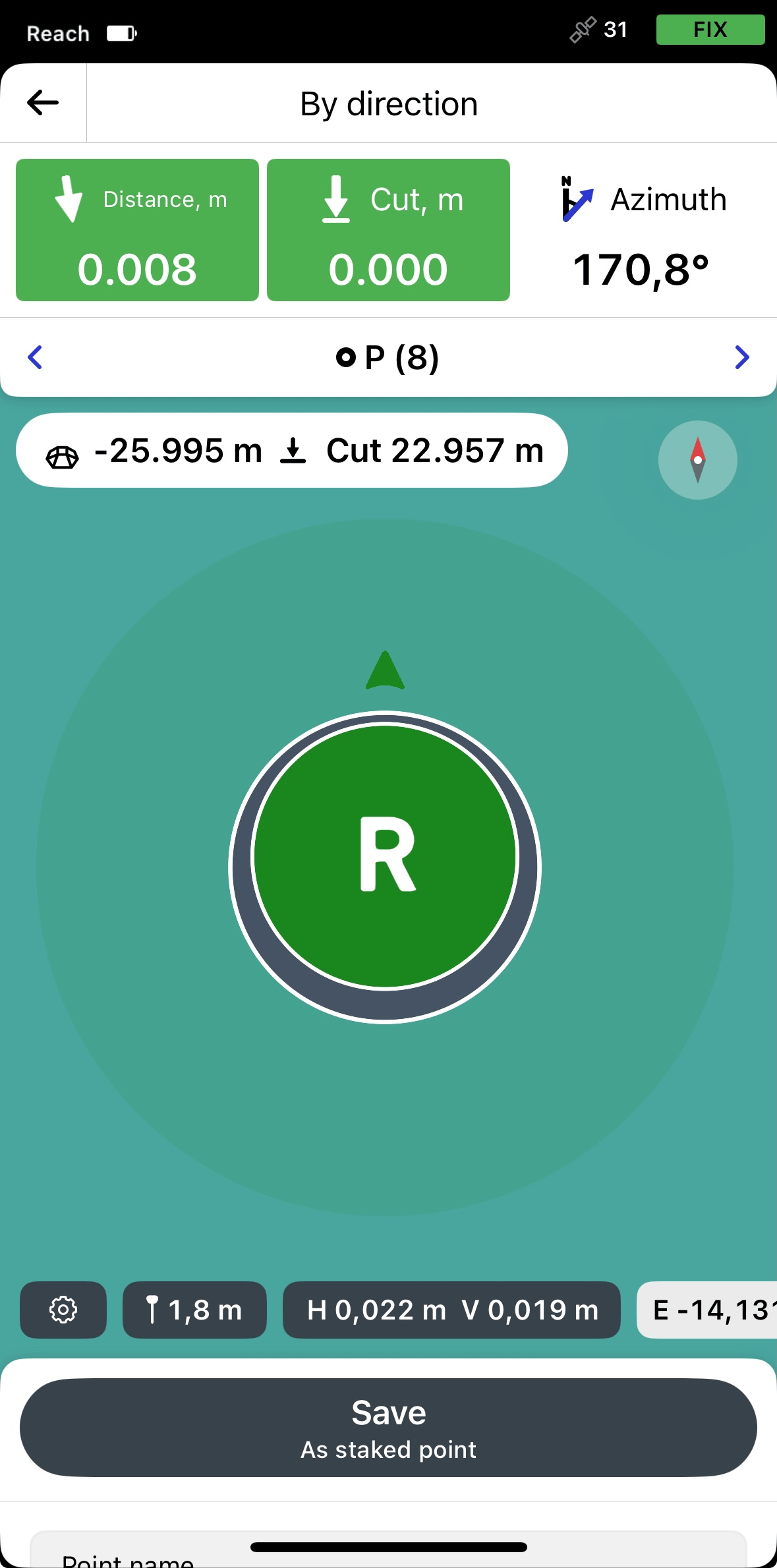
The app displays Cut and Fill values based on both the point elevation and the surface elevation. The main value shown on the plate is calculated relative to the point elevation. A second value, shown in the chip below the surface height, is calculated relative to the surface.
If you are staking out a point above a surface, the app uses the surface elevation at that location to calculate the Cut and Fill value shown in the chip. When a vertical offset is applied to the surface, this value updates to reflect the adjusted surface elevation.

- note
This step is optional.
In the survey settings, set a vertical offset to work with a single DTM file at different stages of the project. This ensures the layers align correctly with the current base layer's height:

Move your Reach in the direction of the point. When you get closer, the map zooms in automatically.
noteThe direction arrows on the stakeout plate can help you navigate to the point.
Move your Reach so that the bull’s eye turns green, showing that your Reach is less than 2.5 cm (0.08 ft) away from the point you are staking out.
noteEnsure the pole isn’t tilted if you’re using Reach receiver model other than Reach RS3.
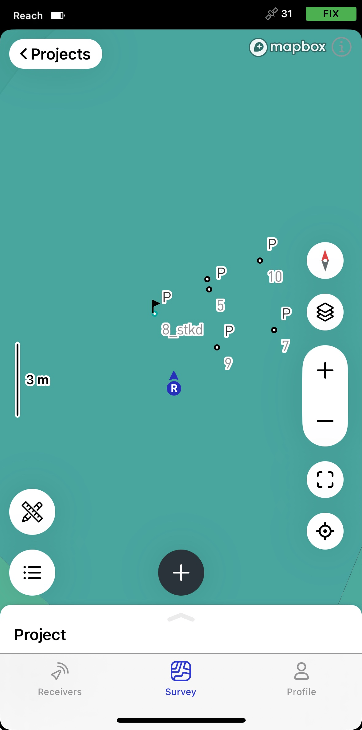
To fix the actual position of a point with deltas, the coordinate differences between the design and the staked points, tap Save as staked point. The staked point will get its design point name with a '_stkd' suffix. You can enter a different name for this point or change it any time.
The staked point will be saved in your project and marked with a flag. The design point that has a stake will be highlighted in blue. These points will appear in the list of objects and on the map as follows:
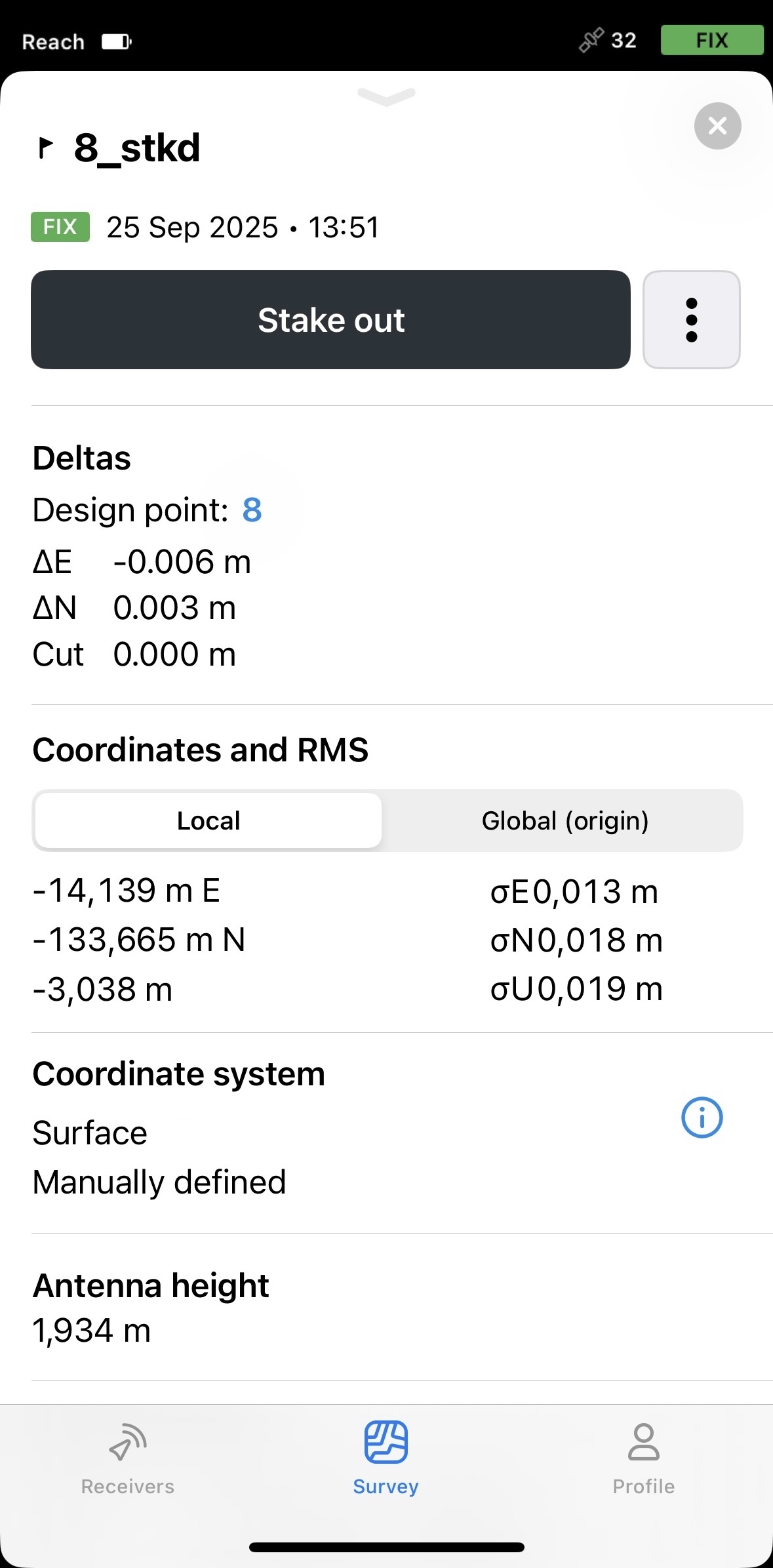
To see the deltas, the coordinate differences between the design and the staked points, tap the staked point and swipe up the Stake out field.
 tip
tipYou can prepare a stakeout report to document the results of your stakeout work. The report includes the design, staked point pairs, and their coordinate differences. Surface elevation data is not yet included but will be added in a future release. For more information on how to generate and use stakeout reports, refer to the Prepare stakeout reports guide.
Switch to another point by tapping the arrow buttons in the Stakeout navigation area.
Tap the back button on the Stakeout plate to finish staking out the point.
To stake out lines
Choose line stakeout mode.
 note
noteIn this guide, we use the Along line mode, which lets you stake out the full line with 3D distance, 2D offset, and cut/fill values. This mode is enabled by default. To learn more about other modes, see the Stake out lines guide.
Select the line you want to stake out on the map or from the object list.
 tip
tipThe selected line will be highlighted in blue on the map.
- note
This step is optional.
In the survey settings, set a vertical offset to work with a single DTM file at different stages of the project. This ensures the layers align correctly with the current base layer's height:
 note
noteThe app displays Cut and Fill values based on both the point elevation and the surface elevation. The main value shown on the plate is calculated relative to the line elevation. A second value, shown in the chip below the surface height, is calculated relative to the surface.
Move your Reach so that the navigation sections turn green, showing that your Reach is less than 2.5 cm (0.08 ft) away from the line you are staking out.
 note
noteEnsure the pole isn't tilted if you’re using Reach receiver model other than Reach RS3.
Watching the Offset plate, check if the line is set out according to the project.

To finish staking out the line, tap the back button on the Stakeout plate.
Emlid Flow automatically remembers the stakeout mode you used the last time.