Working with CAD drawings
Unlock the full set of features for topo, set-out, and as-built surveys
This guide explains how to import CAD drawings into your projects in Emlid Flow 360 and how to stake out the objects within them in Emlid Flow.
Overview
Emlid Flow 360 allows you to import CAD drawings in DXF format into your projects while preserving geometry view, colors, and annotations from CAD software. These drawings can be used as background maps or for stakeout in Emlid Flow, optimizing the design set-out and as-built survey workflows.
When surveying using CAD drawings, you can:
- Stake out polygons, lines, and their segments.
- Stake out block references.
Curved geometries, such as circles or arcs, will be converted to polylines.
Importing CAD drawings
To import a surface file, follow these steps:
You can import CAD drawings into your project only through the Emlid Flow 360 app.
To import your CAD drawing, follow these steps:
-
Open Emlid Flow 360 and go to your project.
cautionYour CAD drawing must use the same coordinate system and measurement units as your project in Emlid Flow 360.
-
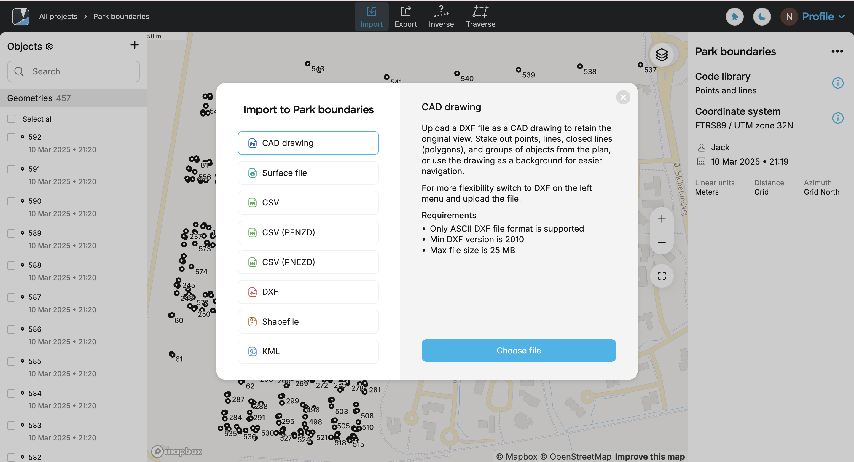
Click the Import button on the top of the screen.
-
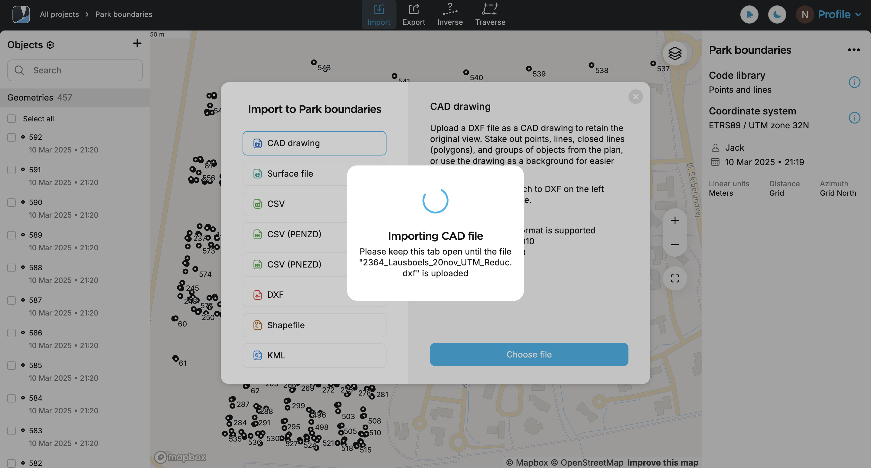
Select CAD drawing and click Choose file.
noteMake sure you have checked the file requirements and your storage is not exceeded.
-
Upload a file in DXF format. Your drawing will appear in the list of objects and on the map. By default, the most recently added drawing from the list is shown.
noteThe drawing may take some time to appear on the map. If it isn’t fully converted or only partially appears, try zooming in on the map.
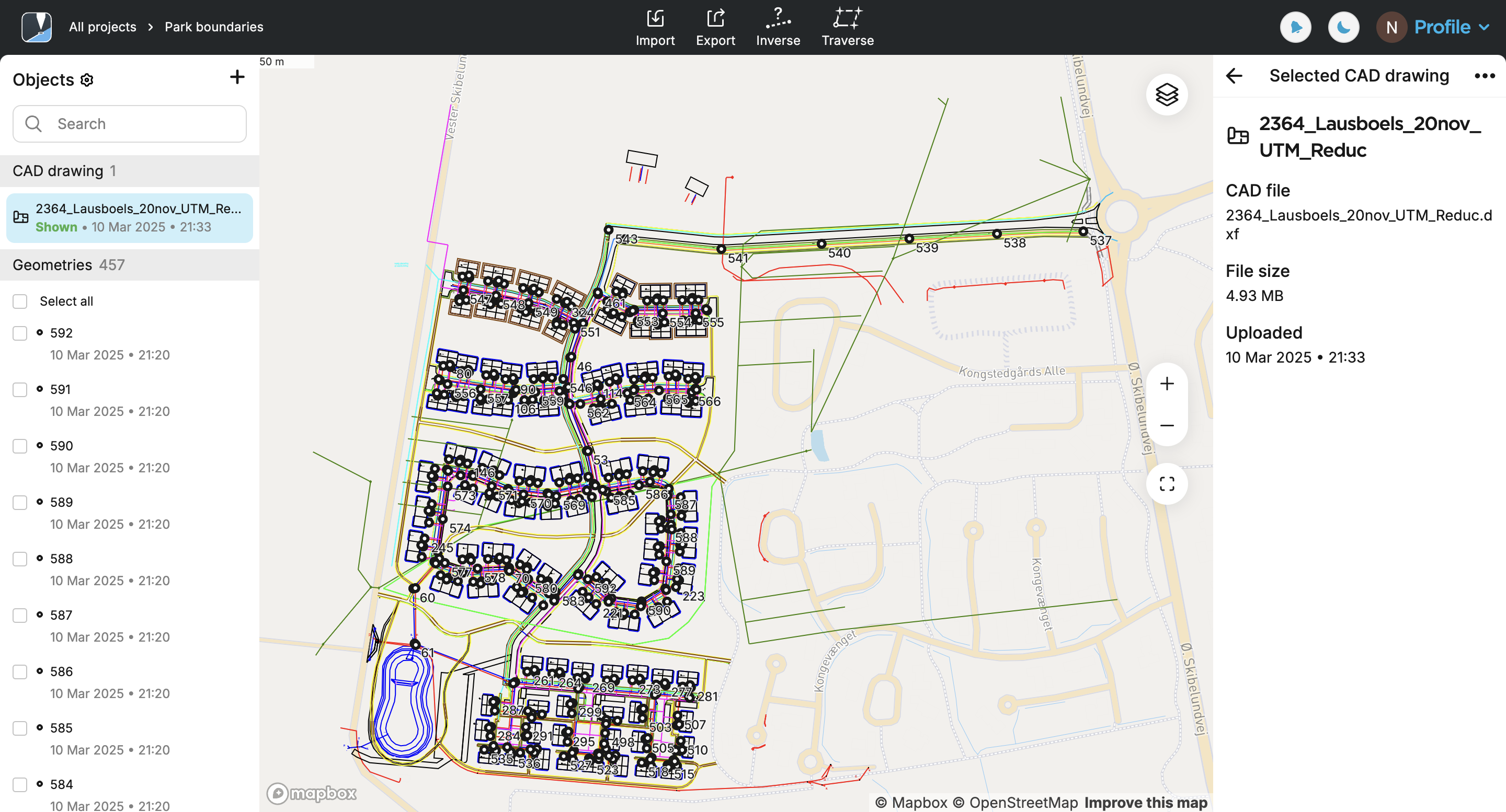
Now, you can access your CAD drawing in the Emlid Flow app.
Accessing CAD drawing in Emlid Flow
After uploading the CAD drawing to your project in Emlid Flow 360, the data will be synchronized, and the drawing will automatically appear in the object list in the Emlid Flow app.
Before starting staking out the objects, ensure that your Reach rover has an established RTK connection and the FIX status.
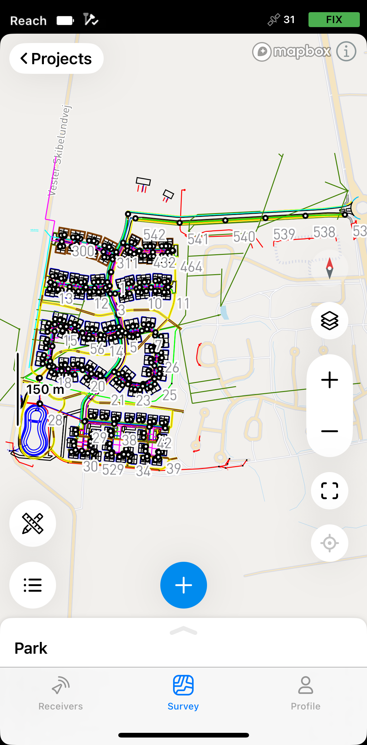
The geometries are available for stakeout only when the CAD drawing is active. To activate or hide a drawing from the object list, tap the eye icon.
Curved geometries, such as circles or arcs, are converted to polylines.
For stakeout, follow the workflows below depending on the type of the geometry.
Staking out points, line vertices, block references
The Stakeout tool has two modes that you can choose between as you navigate to the point you want to stake out:
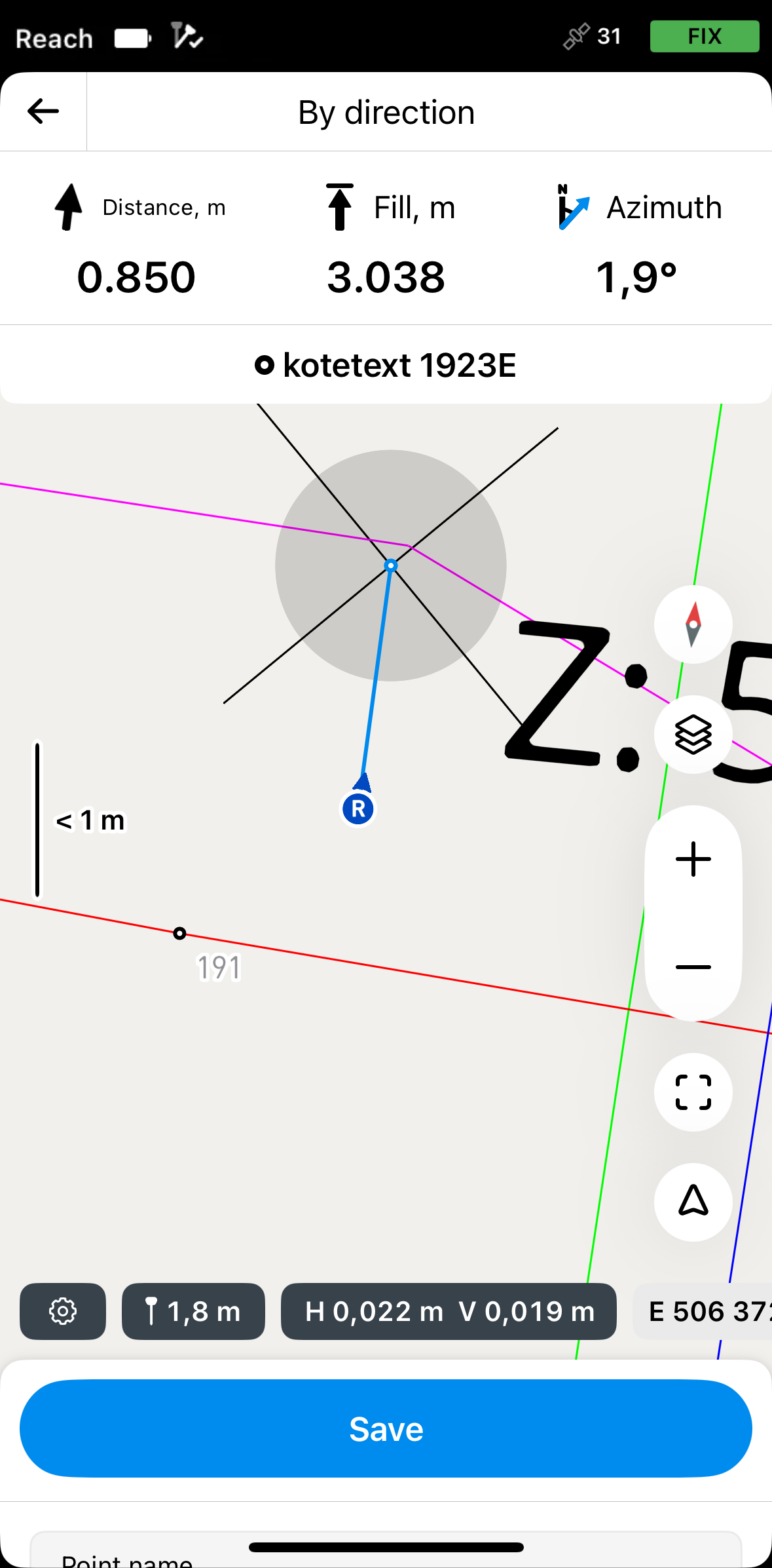
By direction
In this mode, the rover is always centered on the map, and the map rotates so that the heading is always forward. The stakeout plate shows distance and features azimuth, which shows the direction from the rover to the projected point on a line. This is the default mode and it is indicated by the arrow on the Mode button in the lower right corner of the screen.
If you’re using Reach receiver model other than Reach RS3, walk with it for a while to orient it.
By distance
In this mode, the rover is not centered on the map and the stakeout plate shows direction by separating it into North/South and East/West directions and corresponding distances from the rover to the target point on the line. This mode is indicated by the line in the square on the Mode button in the lower right corner of the screen.
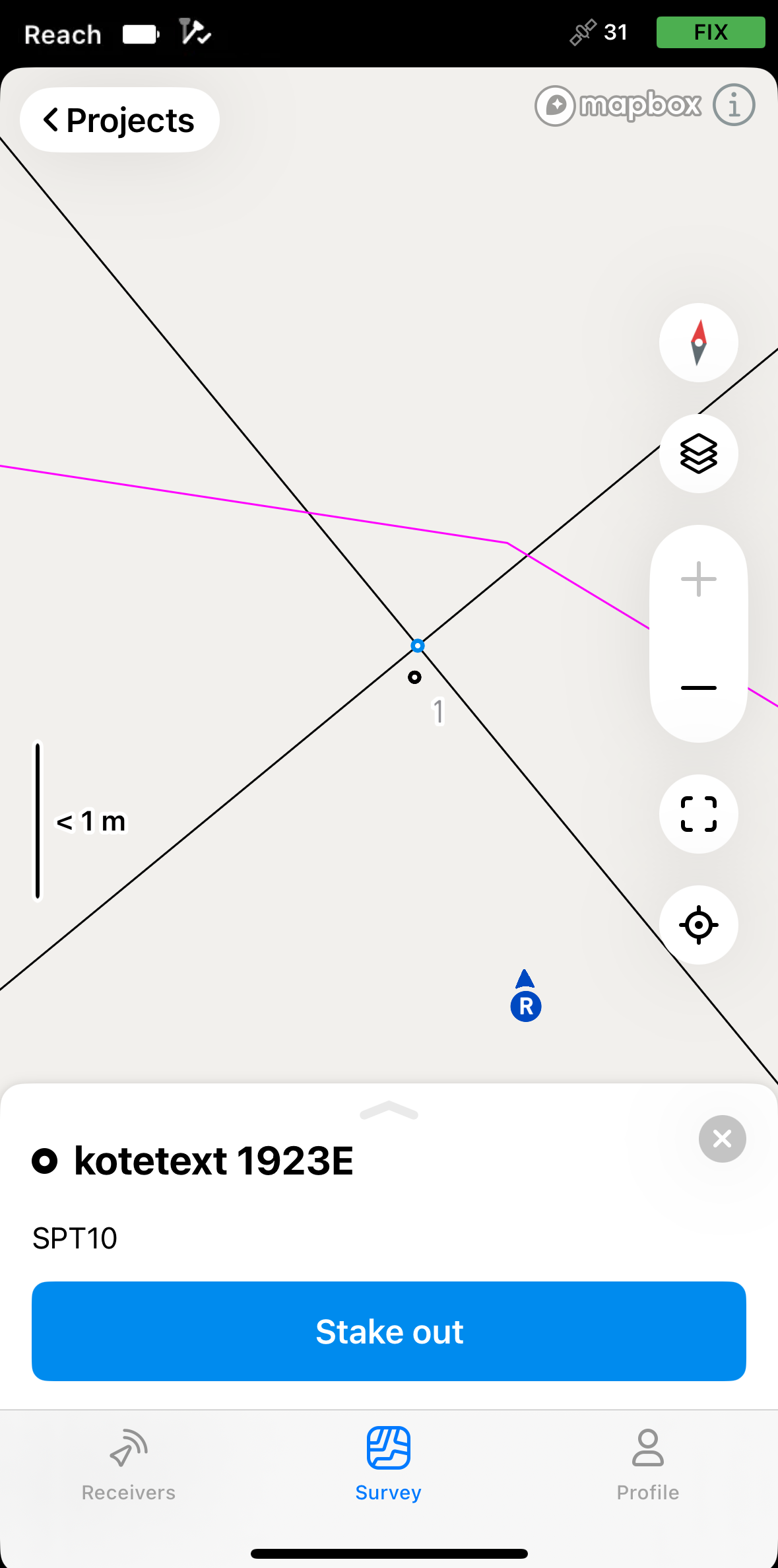
To stake out a block reference on the CAD drawing, follow the steps below:
-
Tap the block reference you want to stake out on the map. You will see its center point highlighted in blue.
noteCAD drawing geometries are only accessible from the map.
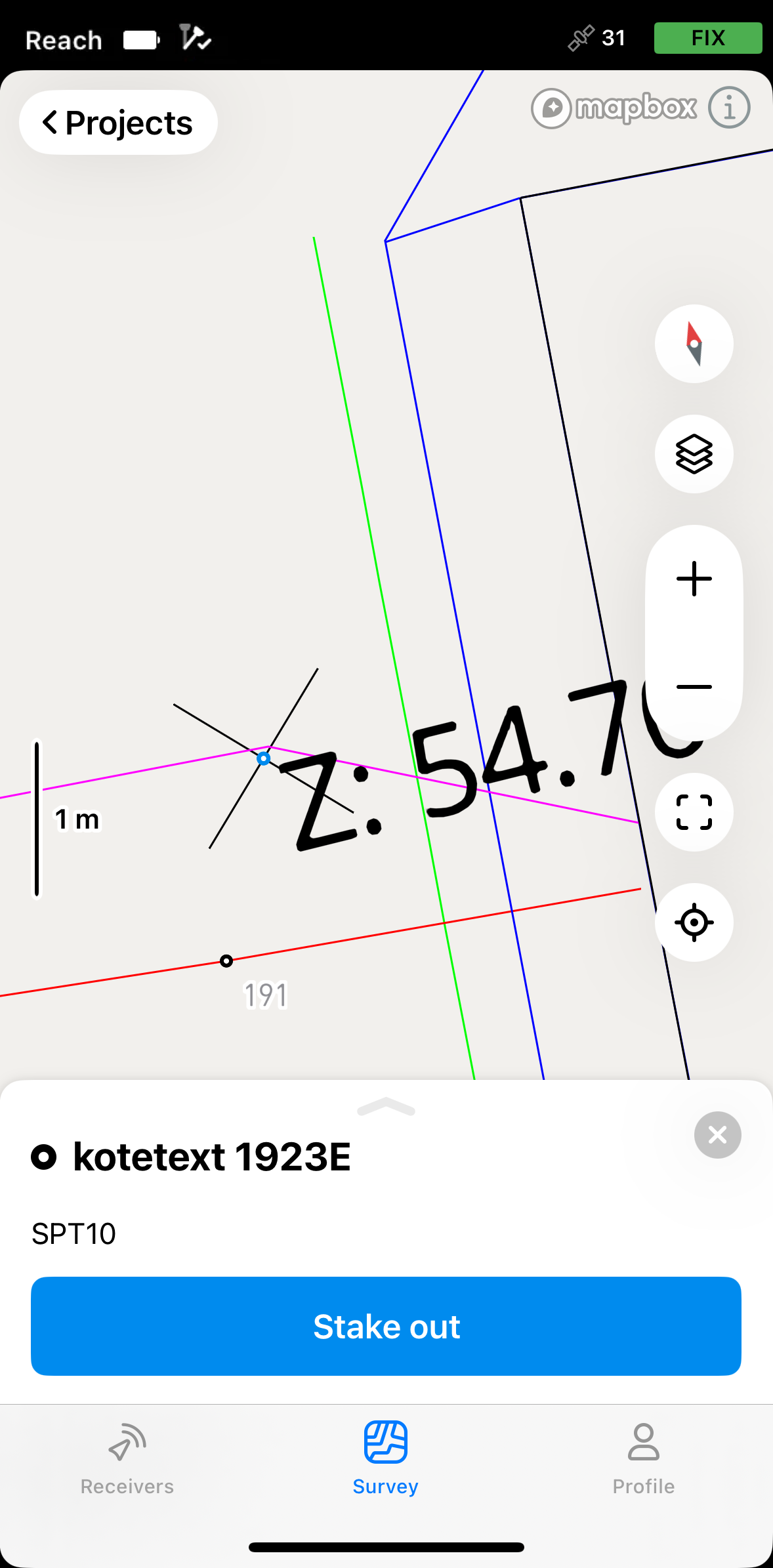
-
Tap the Stake out button.
-
Move your Reach in the direction of the point. When you get closer, the map zooms in automatically.
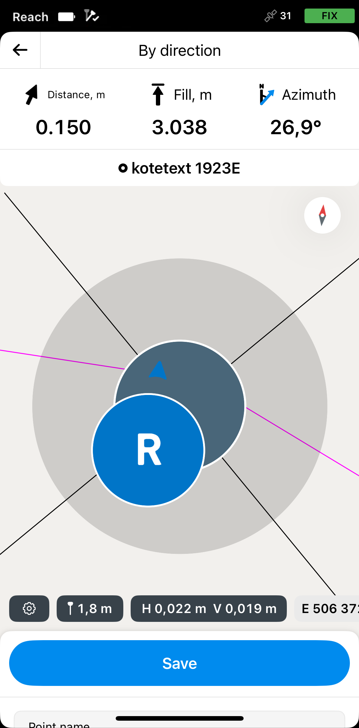 note
noteThe direction arrows on the stakeout plate can help you navigate to the point.
-
Move your Reach so that the bull’s eye turns green, showing that your Reach is less than 2.5 cm (0.08 ft) away from the point you are staking out.
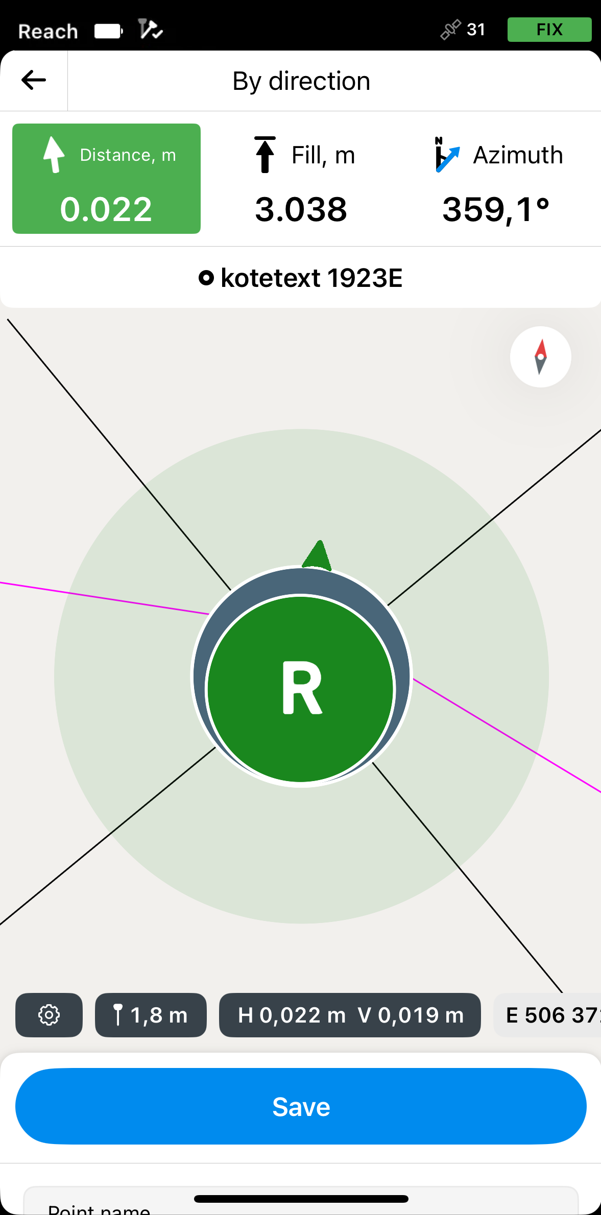 note
noteEnsure the pole isn’t tilted if you use the Reach receiver model other than Reach RS3.
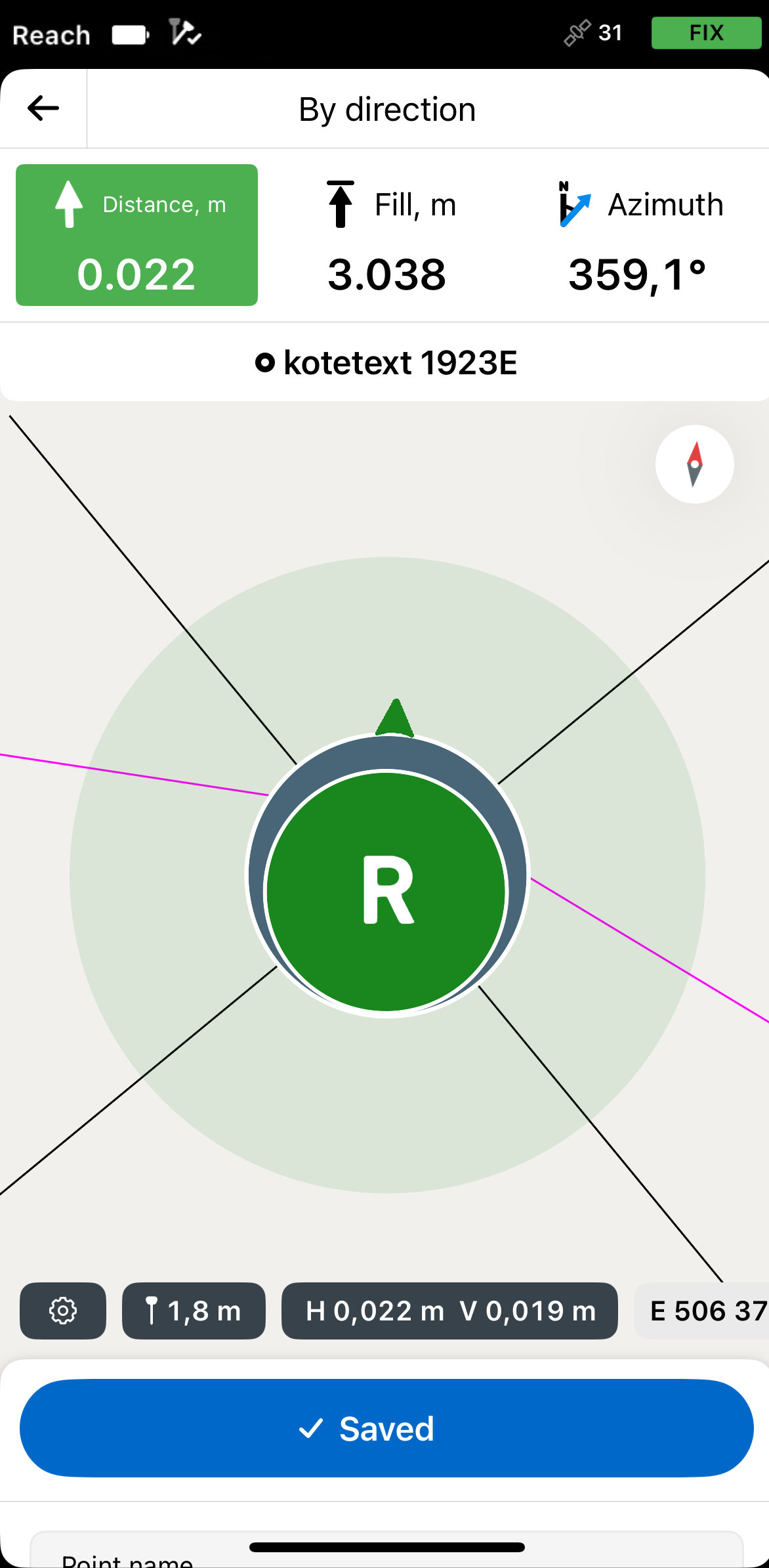
-
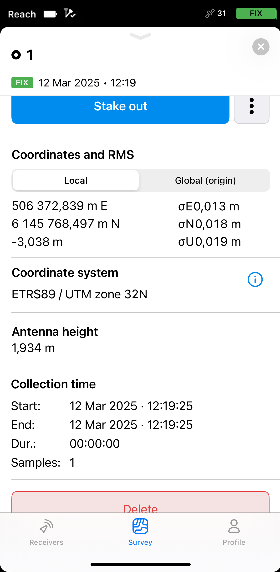
Tap Save. The saved point will appear on the map as a standard point and will be assigned an ordinal number. To view its information, tap the point and swipe up the drawer.
noteThe saved point is independent of the CAD drawing and is stored in the project.
-
Tap the back button on the Stakeout plate to finish staking out the block reference. Select another geometry on the map for stakeout and repeat the steps.
Staking out lines, polygons, and their segments
The workflow for staking out lines, polygons, and their segments is the same. This guide demonstrates the process using a line from a CAD drawing as an example.
Choosing line stakeout mode
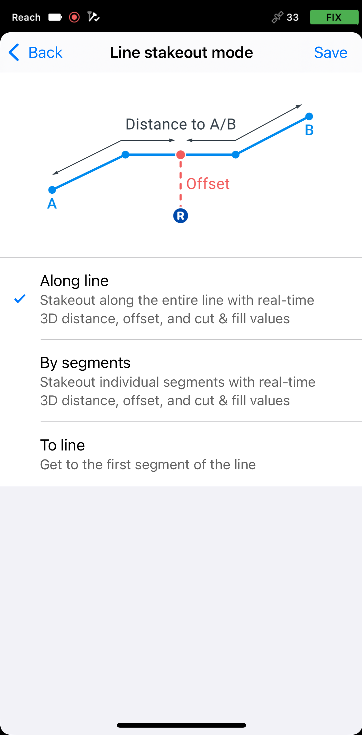
The Line stakeout tool has three modes:

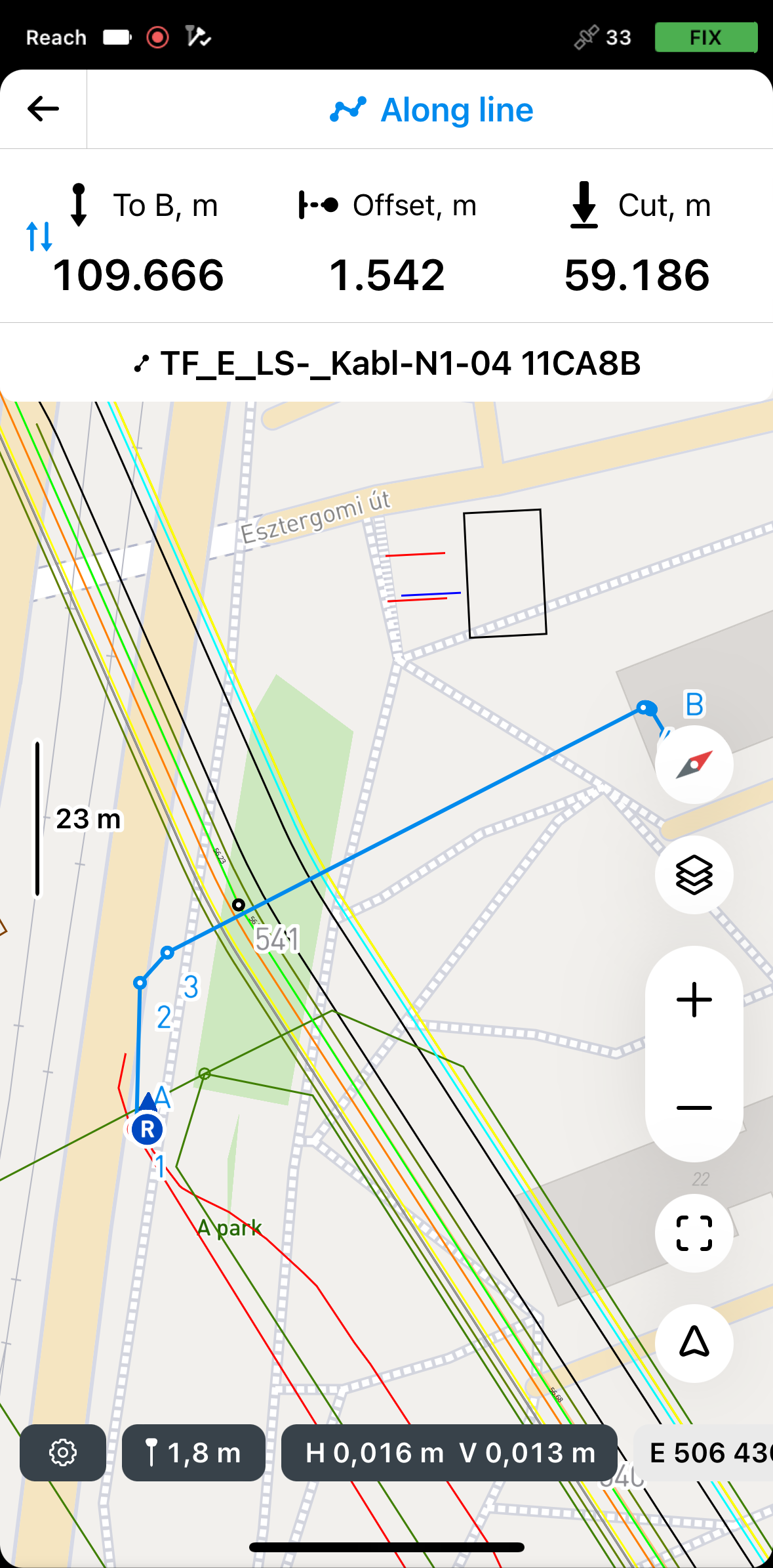
Along line
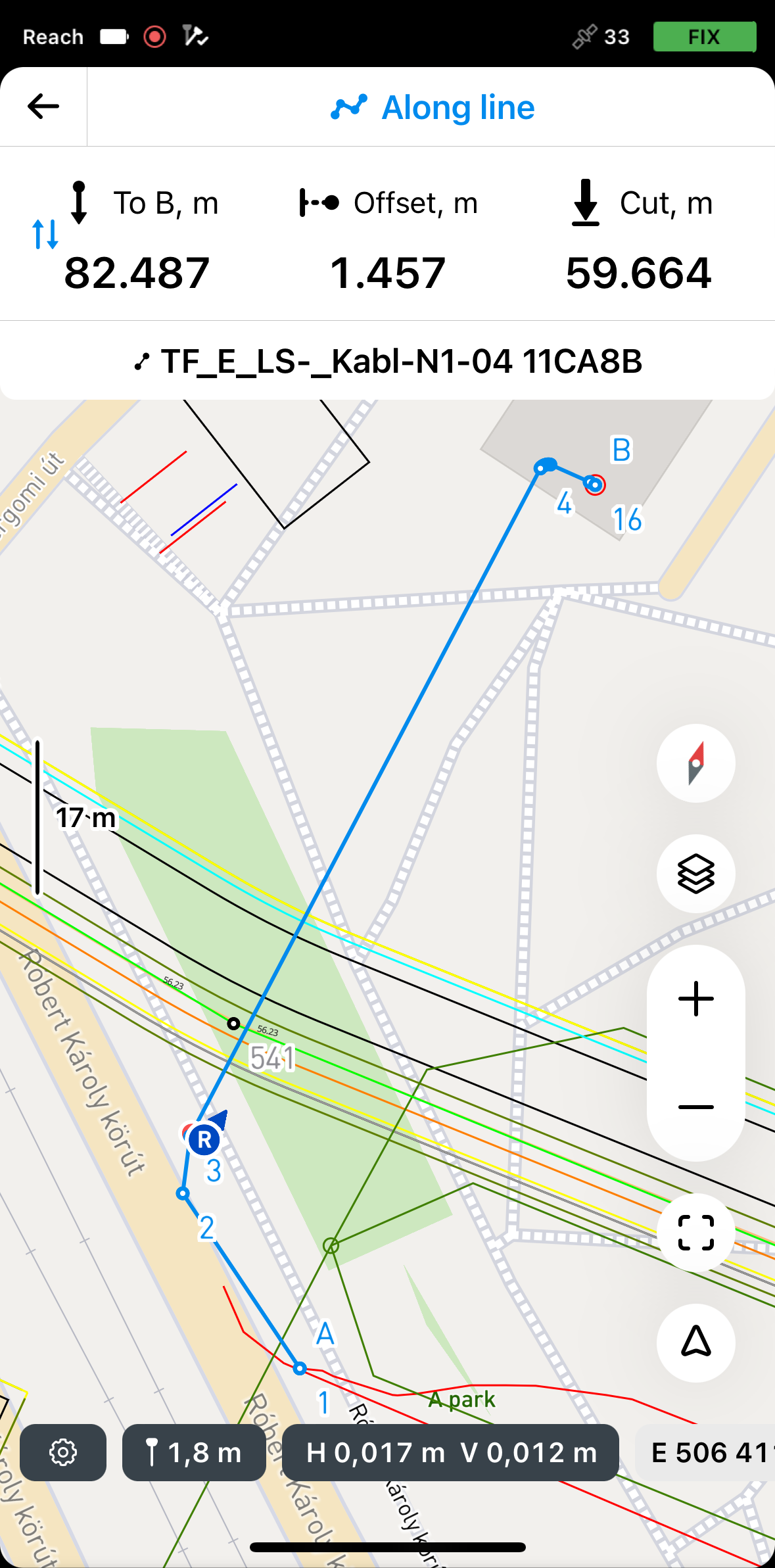
In this mode, you can stake out the entire line with 3D distance, offset, and cut and fill values. It is activated by default.
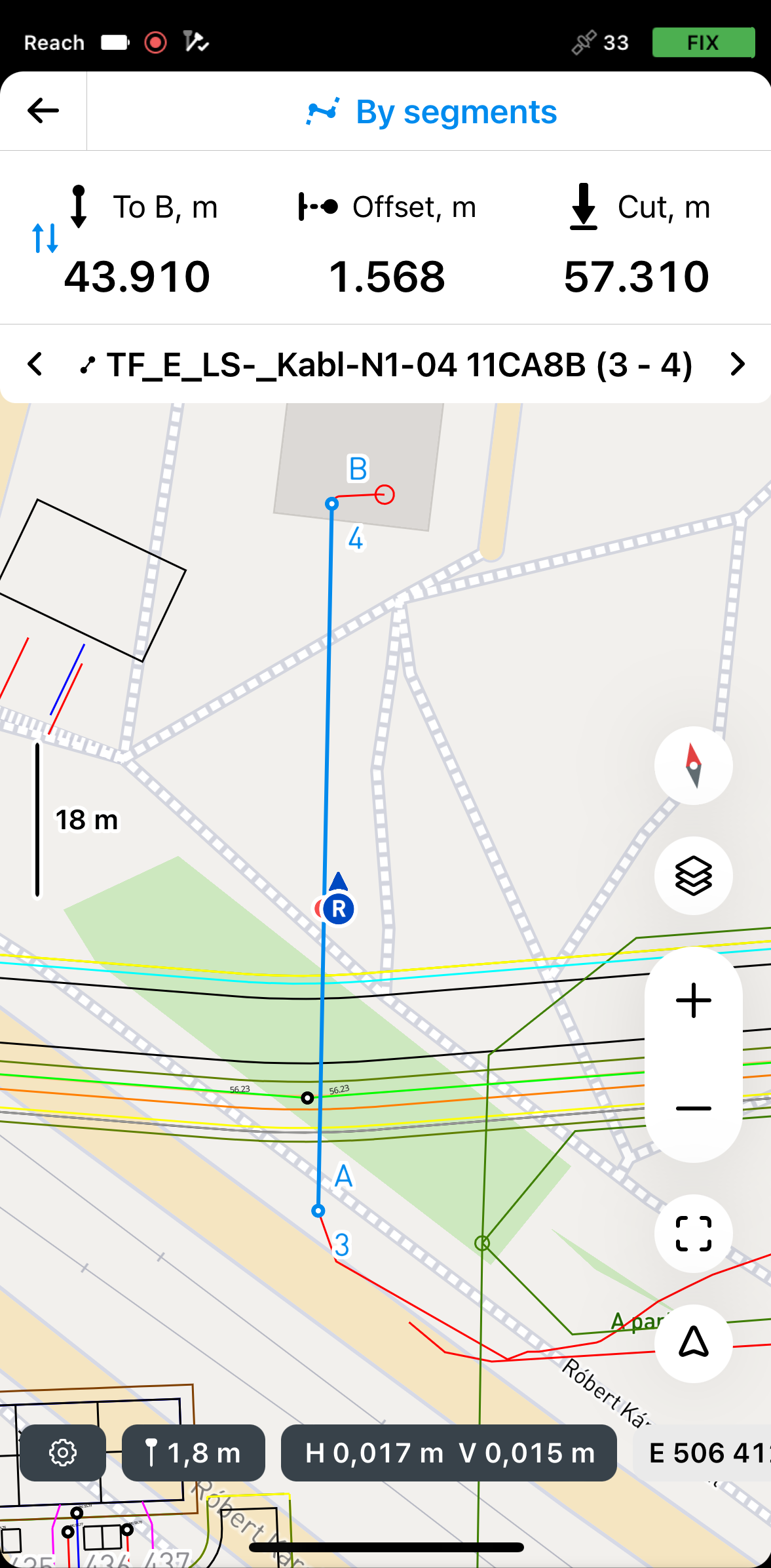
By segments
In this mode, you can stake out individual segments with 3D distance, offset, and cut & fill values.
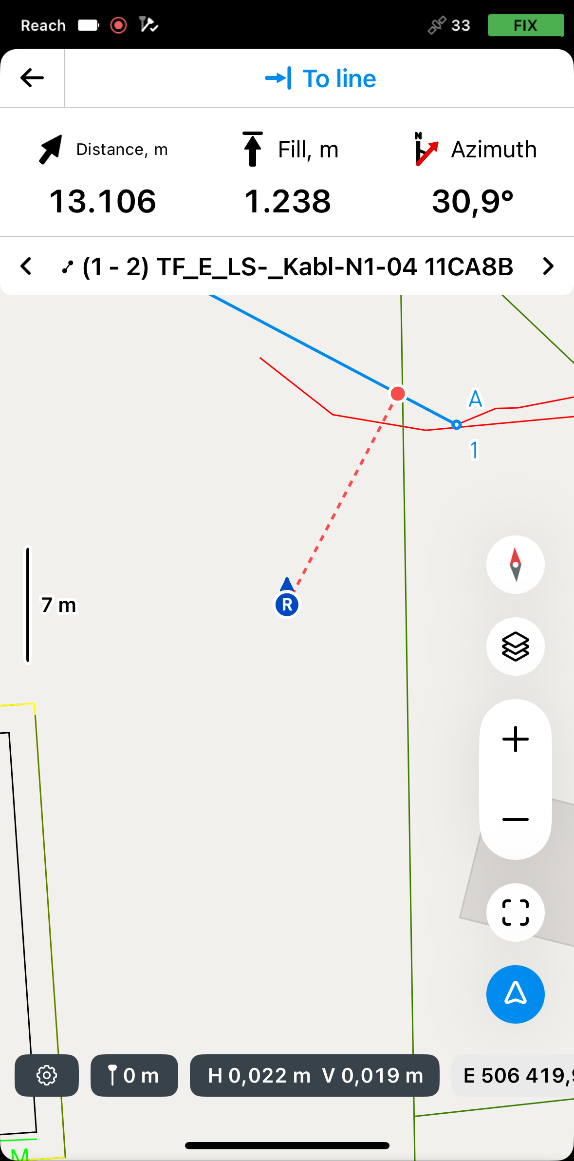
To line
In this mode, you can receive guidance on locating a line, polygon, or segment on the site. You can also select the first point of the line and stake it out separately to reach the starting position more easily.
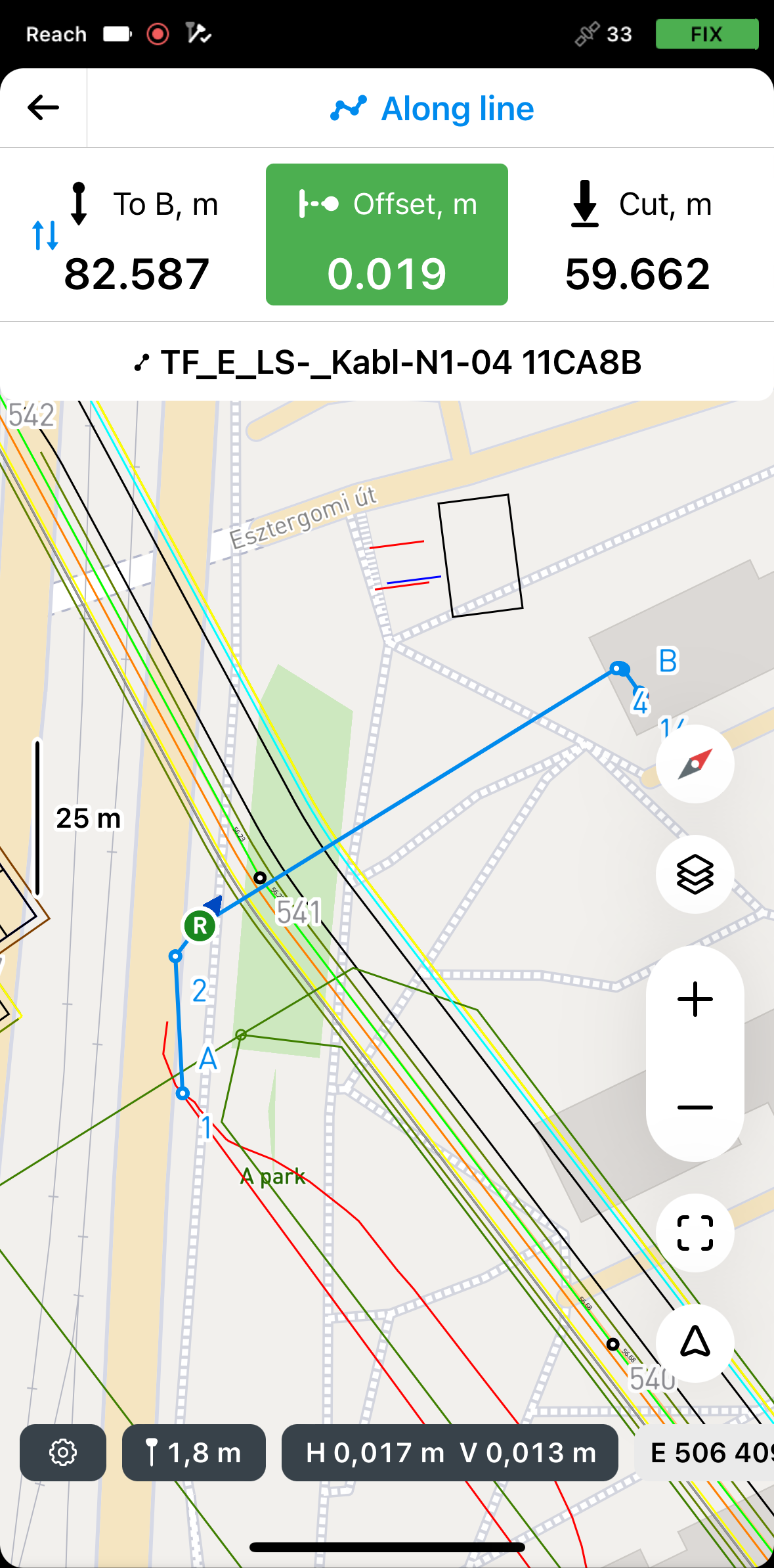
Staking out lines using Along line mode
To stake out the entire line using the Along line mode, do as follows:
-
In Emlid Flow, open your project.
-
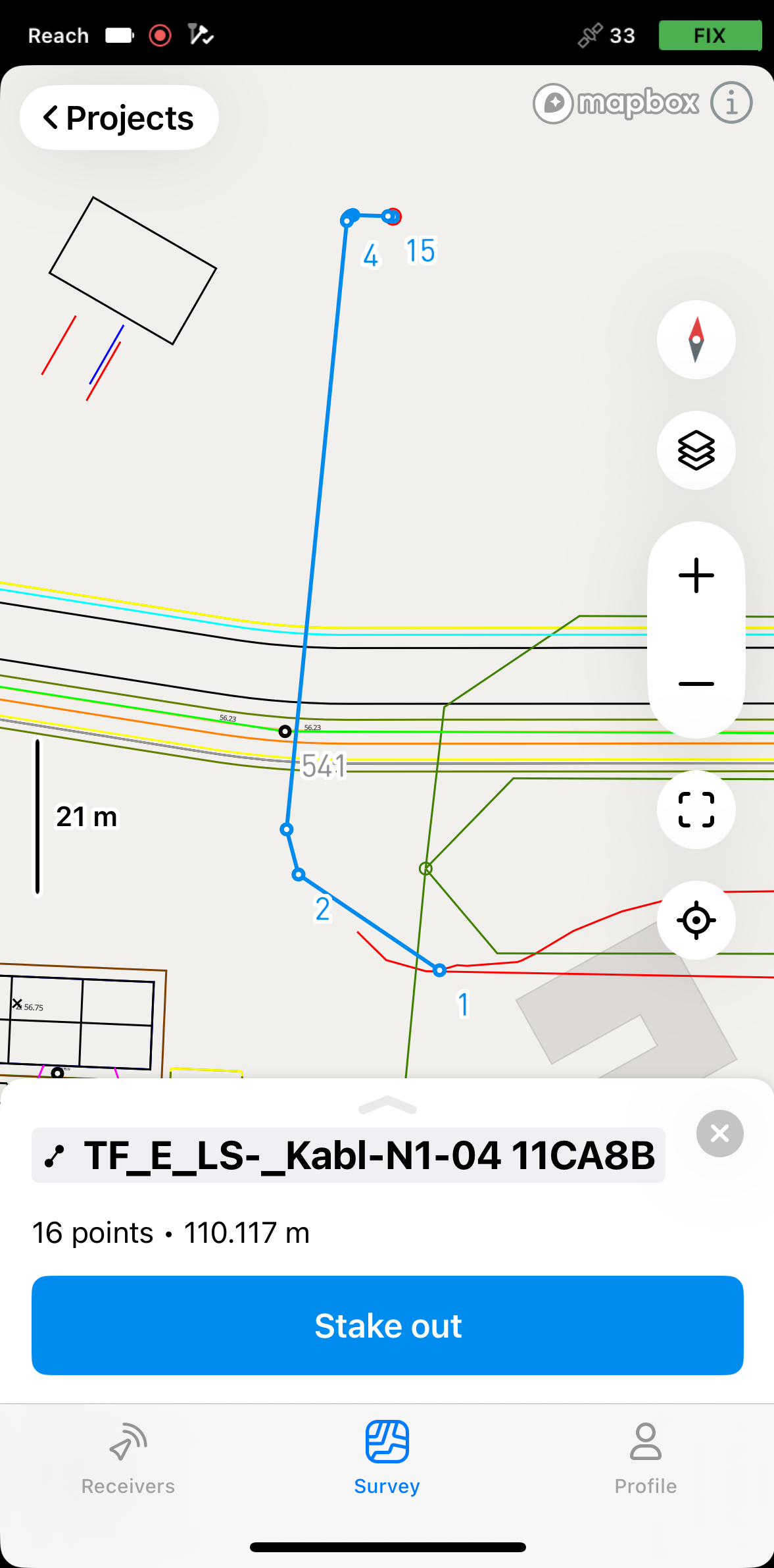
Choose a line on the map or from the list. The selected line will be highlighted in blue on the map.

-
Tap the Stake out button. The Along line mode is applied by default. The line will get the A and B labels at the start and the end points.
 note
noteEmlid Flow remembers the last mode used. If you’ve previously used the Line stakeout tool and a different mode is active, tap the top of the Stakeout plate or tap the survey settings to access the menu with all available modes, then select Along line.
-
Tap the To B section to choose the end of the line from which the stakeout will begin.
Now, you can stake out right over the line or stake out with the offset:
Staking out over line
To stake out over the line, do the following:
-
Move your Reach so that the Offset section turns green, showing that your Reach is less than 2.5 cm (0.08 ft) away from the line you are staking out.
 note
noteEnsure the pole isn't tilted if you use a Reach receiver model other than Reach RS3.
-
Watching the Offset section, check if the line is set out according to the project.
tipYou can also stake out a line with a chainage watching the To A or To B section.
-
Watching the Cut & Fill section, check the height value, if necessary.
-
To finish staking out the line, tap the back button on the Stakeout plate.
Staking out with offset from reference line
-
Position your Reach at the required distance from the line.
 tip
tipThe offset plate section turns green when your Reach is less than 2.5 cm (0.08 ft) away from the line you are staking out.
-
Watching the Offset plate, continue staking out the line.
-
Watching the Cut & Fill section, check the height value, if necessary.
Once you've finished staking out the line, you can either tap another line on the map to start a new stakeout or tap the back button to exit the Line stakeout tool.
Staking out lines using By segments mode
To stake out segments of a line or polygon using the By segments mode, follow the steps below:
-
In Emlid Flow, open your project.
-
Tap the Stake out button. The Along line mode is applied by default. The segment will get the A and B labels at the start and the end points.

 note
noteEmlid Flow remembers the last mode used. If you’ve previously used the Line stakeout tool and a different mode is active, tap the stakeout plate to view all available modes.
-
To access the modes, tap the stakeout plate, select By segments, and tap Save.

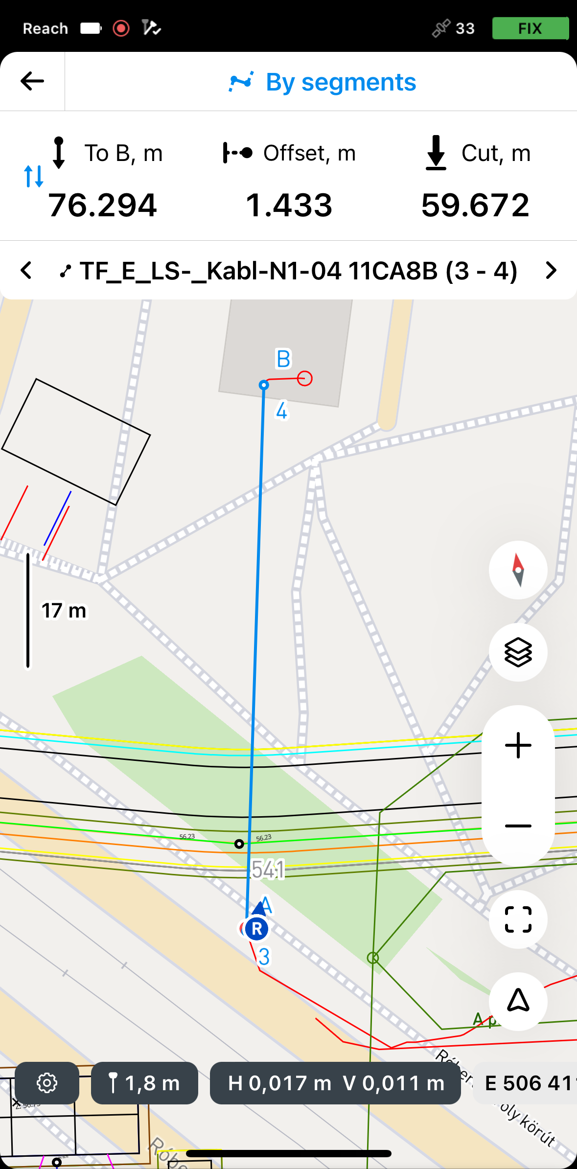
By default, the stakeout process begins from the nearest segment. To stake out a specific segment, use the arrows on the Stakeout plate to navigate to the desired segment.
-
Tap the To B section to choose the end of the line from which the stakeout will begin.
Now, you can stake out right over the segment or stake it out with the offset:
Staking out over segment
To stake out over the segment, do as follows:
- Move your Reach so that the Offset section turns green, showing that your Reach is less than 2.5 cm (0.08 ft) away from the line you are staking out.
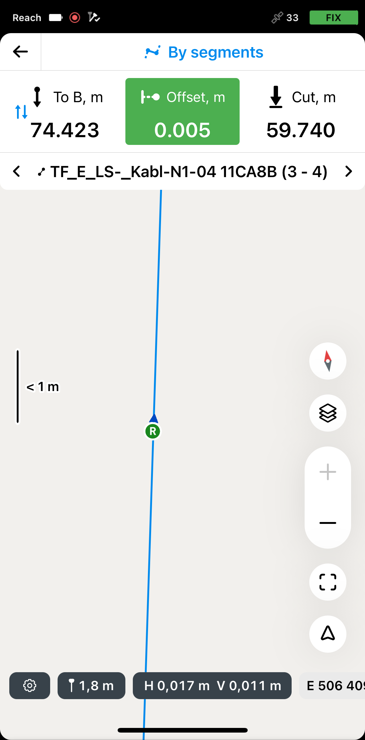
Ensure the pole isn't tilted if you use a Reach receiver model other than Reach RS3.
-
Watching the Offset section, check if the segment is set out according to the project.
tipYou can also stake out a segment with a chainage watching the To A or To B section.
-
Watching the Cut & Fill section, check the height value, if necessary.
-
Switch to another segment you want to stake out using the arrow buttons on the Stakeout plate.
-
To finish staking out the segments of a line or polygon, tap the back button on the Stakeout plate.
Staking out with offset from reference line
- Position your Reach at the required distance from the segment watching the Offset section.
The offset plate section turns green when your Reach is less than 2.5 cm (0.08 ft) away from the line you are staking out.
-
Watching the Offset section, continue staking out the segment.
-
Watching the Cut & Fill section, check the height value, if necessary.
-
Once you've finished staking out the segment, switch to another segment you want to stake out using the arrow buttons on the Stakeout plate.
Once you've finished staking out the line or polygon segments, you can either tap another line or polygon on the map to start a new stakeout or tap the back button to exit the Line stakeout tool.
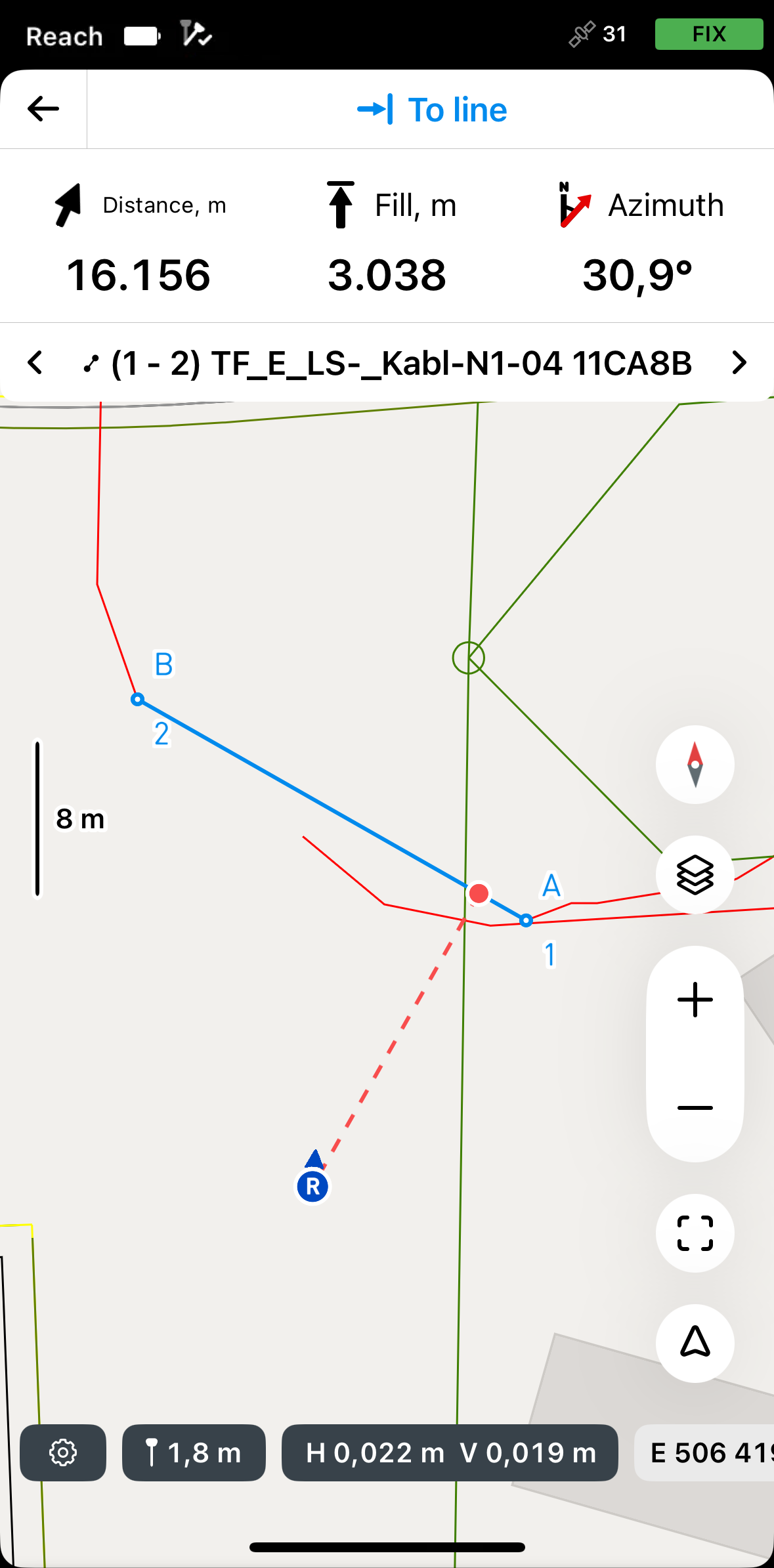
Getting to lines using To line mode
The To line mode is an auxiliary one and helps you navigate to the line’s first segment. You can navigate to your line using the following modes:
By direction
In this mode, the rover is always centered on the map, and the map rotates so that the heading is always forward. The stakeout plate shows distance and features azimuth, which shows the direction from the rover to the projected point on a line. This is the default mode and it is indicated by the arrow on the Mode button in the lower right corner of the screen.
If you’re using Reach receiver model other than Reach RS3, walk with it for a while to orient it.
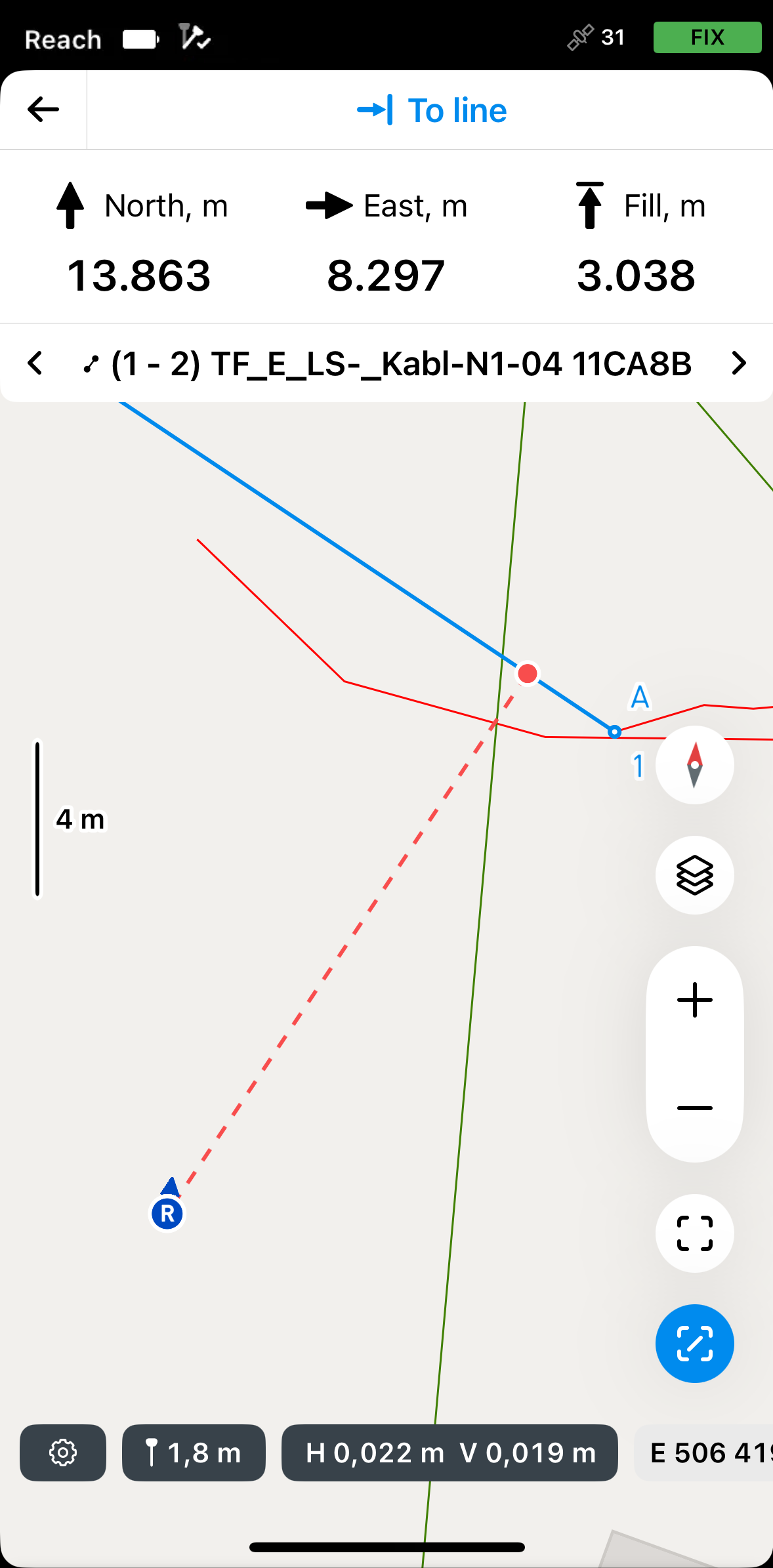
By distance

In this mode, the rover is not centered on the map and the stakeout plate shows direction by separating it into North/South and East/West directions and corresponding distances from the rover to the target point on the line. This mode is indicated by the line in the square on the Mode button in the lower right corner of the screen.
To activate the required mode, do the following:
-
Tap the Mode button in the lower right corner of the screen. It will turn blue.
-
To switch to the required mode, tap the Mode button again.
noteMoving or zooming the map will deactivate the By direction mod. When moving the rover, the map will not move automatically.
To navigate to the line, do as follows:
-
In Emlid Flow, open your project.
-
Choose a line on the map or from the list. The selected line will be highlighted in blue on the map.
-
Tap the Stake out button. The Along line mode is applied by default.
 note
noteEmlid Flow remembers the last mode used. If you’ve previously used the Line stakeout tool and a different mode is active, tap the Stakeout plate to view all available modes.
-
To access the modes, tap the Stakeout plate, select To line, and tap Save.
-
Move your Reach so that the Distance section turns green, showing that your Reach is less than 2.5 cm (0.08 ft) away from the line you are staking out.
 note
noteEnsure the pole isn't tilted if you use a Reach receiver model other than Reach RS3.
Once you are on the line, switch to Along line or By segments mode to continue the stakeout process.