Сonfiguring Reach UAV Kit for PPK Mapping
This guide explains how to set up your Reach receivers for PPK mapping with UAV.
We recommend checking the How PPK works article before you start.
Overview
To configure Reach UAV kit for PPK mapping, you will need the following:
- Reach RS2/RS2+ or Reach RS+ base
- Reach M2/M+ rover with GNSS antenna
- Hot shoe adapter (HSA) for a camera
- Any camera that provides hot shoe access (e.g. Sony, Canon, Nikon)
Reach RS+ cannot act as a base for a Reach M2 rover as Reach M2 requires multi-frequency corrections. Still, you can use Reach RS2/RS2+ as a base for Reach M+. Note that you will not get all advantages of the multi-band receiver in this case. You can learn more about the differences between single-band and multi-band receivers in the Single-band VS Multi-band article.
Additionally, you will need a few Ground Control Points (GCPs). To place GCP, a base and a rover are required, or you can use one receiver connected to an NTRIP.
In this guide, we are mostly focused on the GNSS equipment part of the integration. However, you also need a UAV and a PC with a Ground control station and photogrammetric software. There are 2 main requirements for UAV:
- The presence or ability to install a camera with a hot shoe connector
- Functionality allowing triggering the camera: by camera itself or by autopilot
Reach M2/M+ hardware setup
Connecting Reach M2/M+ to a camera using HSA
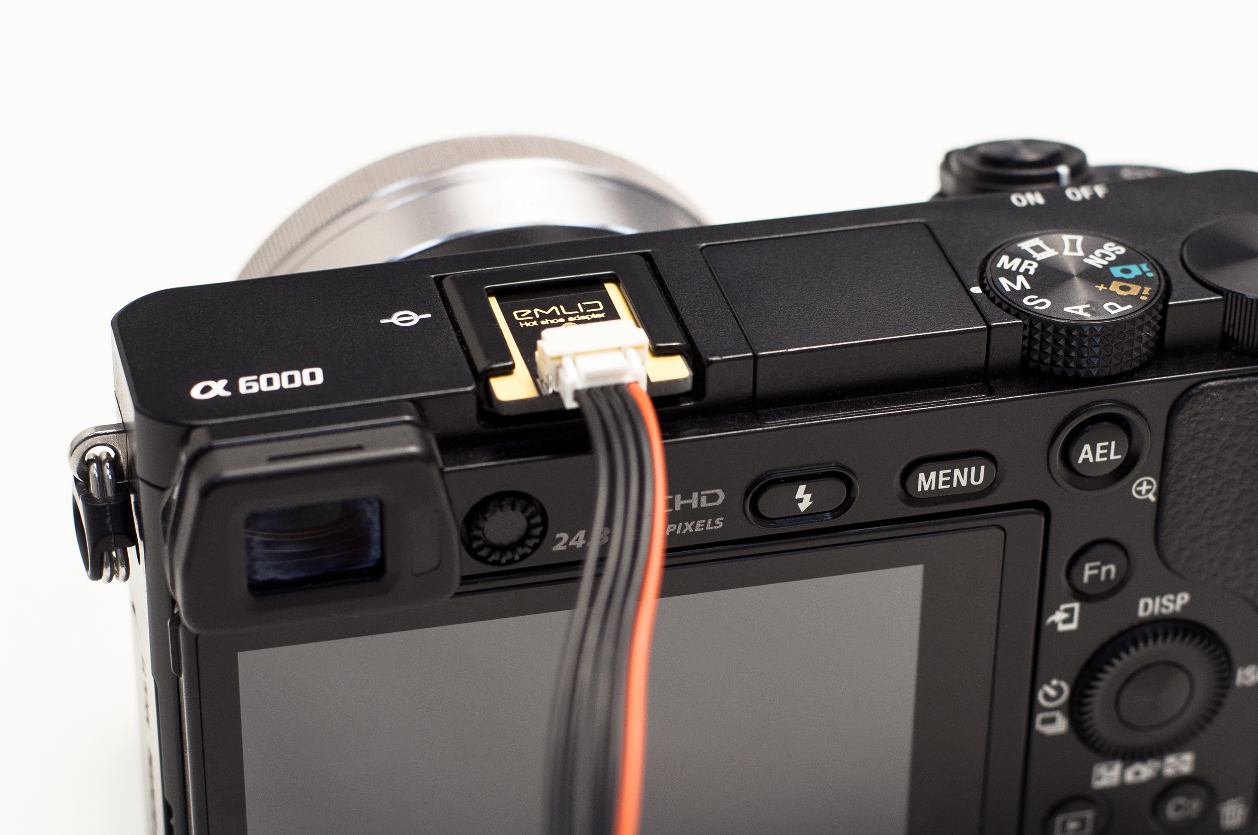
HSA allows Reach M2/M+ to precisely record a time mark at every moment the camera takes a photo.
The camera requires to have a hot shoe for integration with Reach M2/M+. If you use DJI Mavic or Phantom which does not provide hot shoe access, you can always stick to working with GCPs.
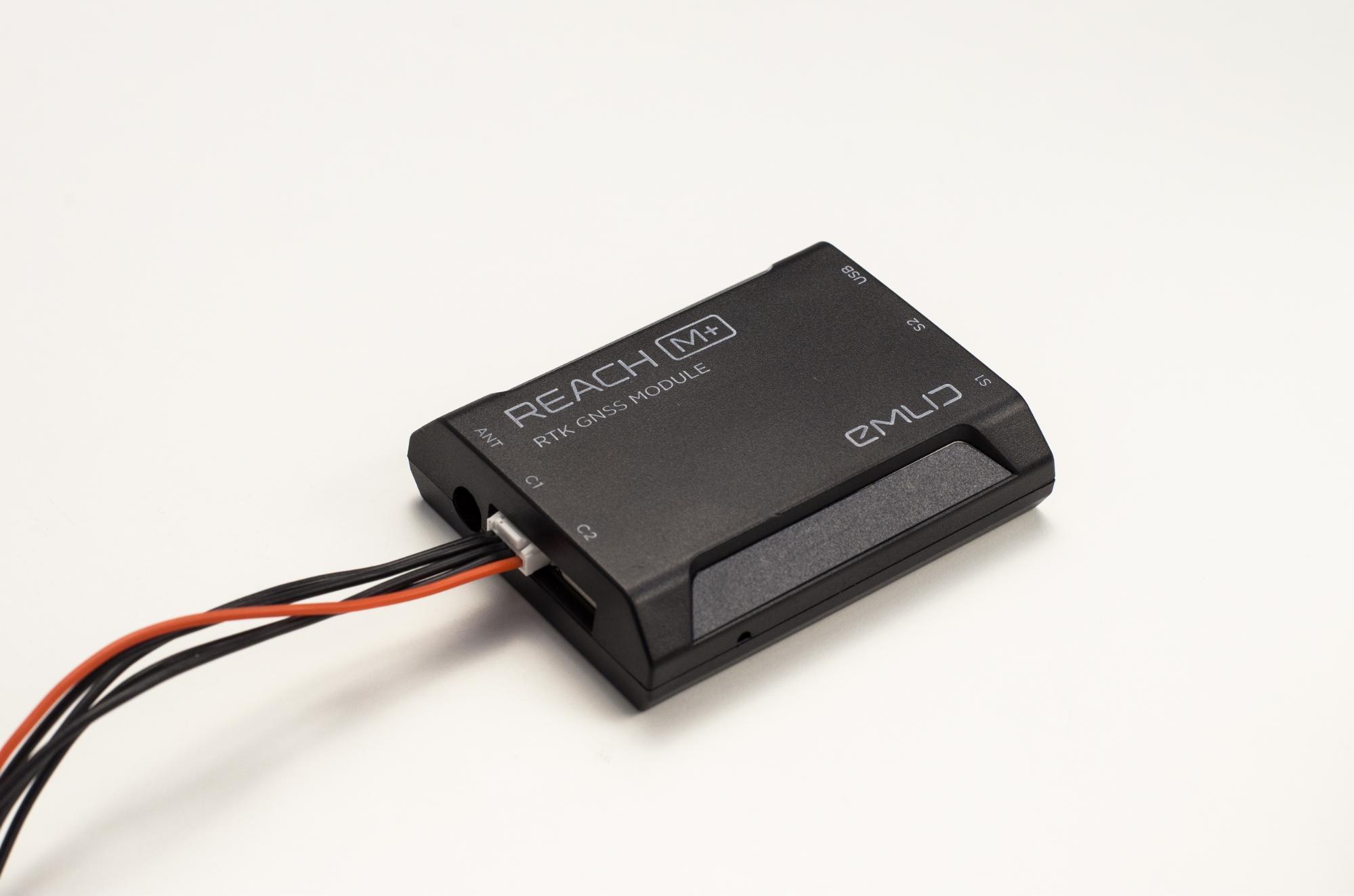
To connect Reach to a camera with a hot shoe adapter use 5-pin JST-GH cable that comes with Reach M2/M+. Plug the hot shoe connector in a camera hot shoe and the JST-GH connector in the С1 port on Reach M2/M+.
Camera triggering
Depending on your application, there are several ways you can trigger a camera.
-
Triggering via camera. Some cameras provide a Timelapse feature that allows taking a photo at regular intervals. If your camera supports this option, we recommend using it as it is the easiest and straightforward way.
tipEach camera uses different ports for triggering. It might be a USB or HDMI port. Read the camera manual to find out how to trigger your camera.
-
Triggering via autopilot. There are several options of triggering the camera via autopilots:
-
Triggering the camera shutter at waypoints. Autopilot can trigger the shutter each time the drone reaches a waypoint. If you use a flight controller based on ArduPilot, check the Camera control in auto missions guide from ArduPilot for more details.
-
Triggering camera shutter at regular intervals. Check the Camera shutter configuration guide from ArduPilot to learn more.
-
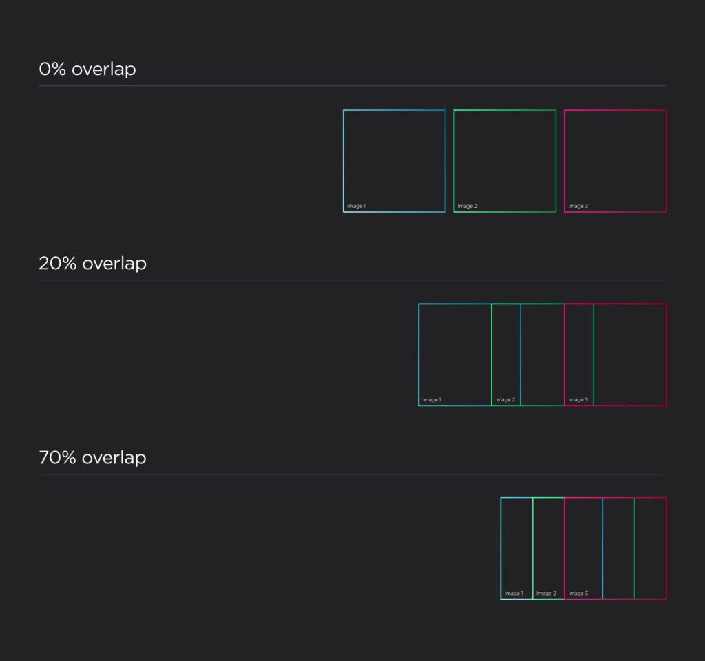
The majority of Ground Control Station software allows and even requires a mission plan preparation before the flight. You need to configure your camera and autopilot the way it obtains images with overlaps. This is necessary because common points in adjacent images are required to create an orthogonal mosaic. We recommend the front overlap to be at least about 60% and the side – about 30%.
Antenna placement
GNSS antenna should be placed on a ground plane. Antenna ground plane should be conductive and at least 70 x 70 mm. A usual metal plate should be good for this purpose.
Helical antennas do not require a ground plane. Still, a ground plane can improve observation quality significantly.
Check the Antenna placement guide to learn more.
Isolating Reach M2/M+ from potential interference
In some cases, you might need to isolate your Reach to ensure the best logging quality. The reason is that the transmitted power of GNSS signals is rather low relative to the possible noise from other hardware components installed on your UAV. It means that the antenna signal strength might be unstable and even sometimes interrupted. Interruption and temporary signal loss on RTK receiver are called cycle slip.
To avoid cycle slips we recommend isolating Reach M2/M+ unit and connect it to the ground to eliminate interference. Also, RC components, such as radio transmitters, might affect the signal as well. Reach should be located as far as possible from them.
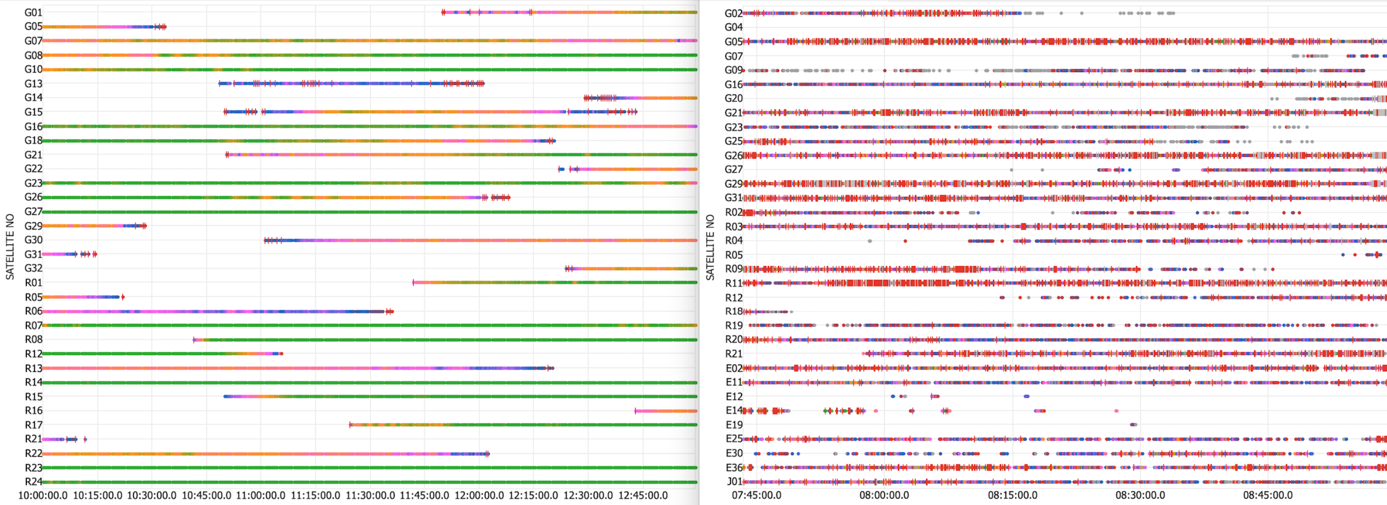
The effects of bad hardware setup are substantial. Poor signal quality with low SNR values, lots of cycle slips pose issues with getting fixed solutions and missing time marks. Take a look at the figures below that demonstrate examples of good (the left picture) and bad (the right one) satellite reception.
You can read more about the signal quality assessment in this section of our docs.
Create a topic on the Emlid community forum in case you experience any difficulties at this stage.
Reach RS2/RS2+/RS+ base setup
Check out the figure below and choose an appropriate location to place Reach RS2/RS2+ or Reach RS+ base station. The basic rules are:
- Good sky angle over 30 degrees
- Away from trees and buildings
- No electricity nearby
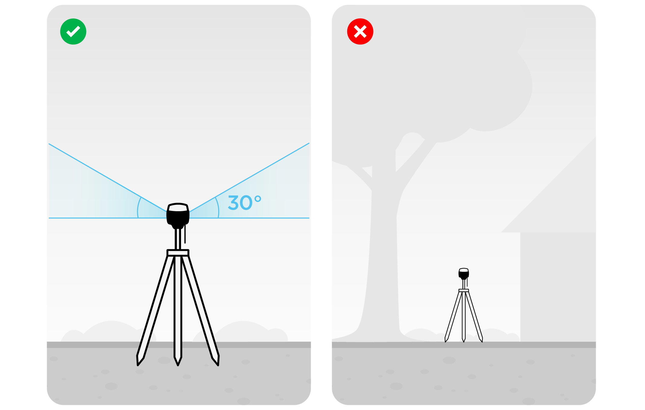
Check the Placing the base guide to learn more.
Configuring base and rover before the flight
Reach M2/M+ rover settings
-
Power your Reach M2/M+ from an external power source or drone battery.
tipCheck the Power supply guide to learn more.
-
Access Reach M2/M+ in the Emlid Flow.
tipCheck the Connecting to Reach and Connecting Reach to the Internet guides to learn more.
-
Go to the RTK settings and configure one of the recommended GNSS selection and update rate for time mark logging:
note- Reach M2
- Reach M+
Reach M2 tracks GPS, GLONASS, GALILEO, QZSS, and BeiDou satellite systems. The data can be logged with 1 Hz, 5 Hz, or 10 Hz update rate.
For a drone flight, it is better to set up the update rate to 10 Hz.
GNSS Selection Reach M+ allowed update rates GPS + GLONASS + GALILEO + SBAS + QZSS 1 Hz GPS + GLONASS + QZSS 5 Hz GPS + GALILEO 5 Hz GPS 10 Hz -
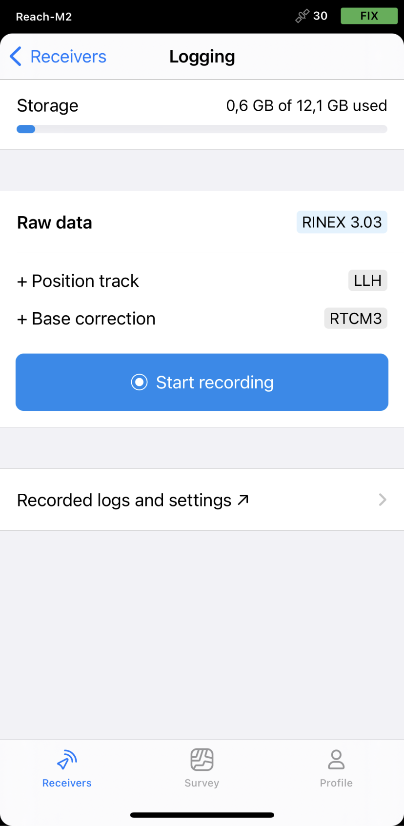
Enable raw data recording on the Logging screen:
Reach RS2/RS2+/RS+ base settings
-
Turn on the Reach RS2/RS2+ or Reach RS+ unit.
-
Access the receiver in Emlid Flow.
-
Go to the GNSS settings screen.
-
Choose the same GNSS as for Reach M2/M+ with 1 Hz GNSS update rate.
-
Enable raw data recording on the Logging screen.
Placing Ground Control Points
Ground Control Points (GCPs) are points with known coordinates on the ground in the area of your interests. GCPs usually help to improve and check the accuracy, get the correct scale and orientation of the map. Also, they are needed for the absolute positioning of your map in relation to the real world around it.
Check the Placing the base guide to learn more about absolute and relative accuracy.
Reach provides centimeter-accurate coordinates in PPK. Also, if you place the base on a point with known coordinates, you will get the coordinates with absolute accuracy. In such a case, GCPs can help you to verify the accuracy.
GCPs should be clearly visible on the drone's images. Make sure the mark is a contrast to its surroundings and that it is big enough. Place a survey pole with a receiver exactly in the center of the mark to take its coordinates.
Enough quantity of GCPs depends on the site area. Usually, it is 5-10 points. There are some basic rules of checkpoints placing:
- They should be allocated evenly in the area where you survey. For example, if you use 5 points, set per one for each corner and the last in the center of the area
- They must not be on the same line
Also, it is great if you have the possibility to place GCPs at the highest and lowest points on site. It helps to perform the correct flat projection.
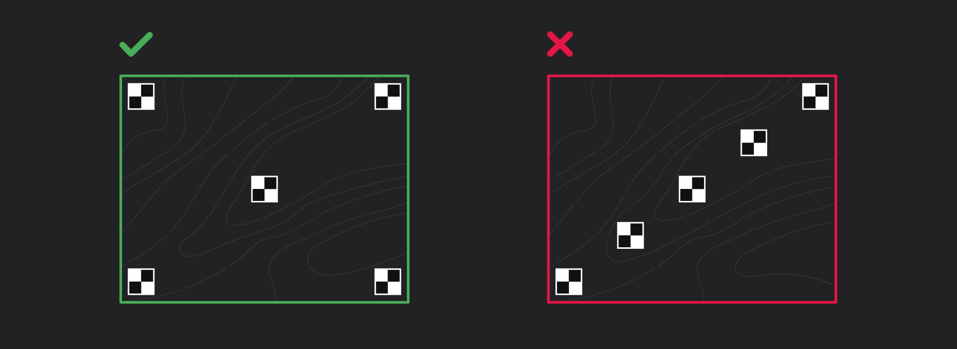
It’s important to meet these requirements if you want to get the same accuracy across the entire plot.
Check the Placing GCPs guide to learn more.
Survey flight
We do not pay much attention to this step due to the differences in the drone flight settings from model to model. Please, check the manual of your drone manufacturer before the flight.
After all the configurations are done, you can proceed to flight with your drone.
Make sure:
- Raw data logging on both Reach M2/M+ and Reach RS2/RS2+ or Reach RS+ units are enabled before the flight.
- Camera triggering is on. Trigger the camera and check the last time mark on the Camera control screen in Settings in Emlid Flow.
When the flight is finished, you can disable logs recording. Before turning the devices off, please wait until the logs processing is done.
You can download raw data logs from both base and rover later on.
As a result of mapping mission with Reach you will have the following dataset:
- Raw log from a base
- Raw log from a rover
- Set of images from a drone
- List of GCPs
Now you can prepare the dataset for further processing.