Trabalho com desenhos CAD
Melhore sua experiência em levantamento topográfico com programação, linhas, mapas de fundo, localização, superfícies e desenhos em CAD
Este guia explica como importar desenhos de CAD para seus projetos no Emlid Flow 360 e como fazer a implantação dos objetos dentro deles no Emlid Flow.
Visão geral
O Emlid Flow 360 permite importar desenhos CAD no formato DXF para seus projetos, preservando a visualização da geometria, as cores e as anotações do software CAD. Esses desenhos podem ser usados como mapas de fundo ou para locação no Emlid Flow, otimizando os fluxos de trabalho de levantamento set-out e as-built do projeto.
Ao fazer o levantamento usando desenhos CAD, você pode:
- Faça a locação de polígonos, linhas e seus segmentos.
- Locação de referências de blocos.
As geometrias curvas, como círculos ou arcos, serão convertidas em polilinhas.
Importação de desenhos CAD
Para importar um arquivo de superfície, execute os passos a seguir:
Você só pode importar desenhos CAD para o seu projeto através do aplicativo Emlid Flow 360.
Para importar seu desenho CAD, execute os passos a seguir:
-
Abra o Emlid Flow 360 e vá para o seu projeto.
cautionSeu desenho CAD deve usar o mesmo sistema de coordenadas e unidades de medida que seu projeto no Emlid Flow 360.
-
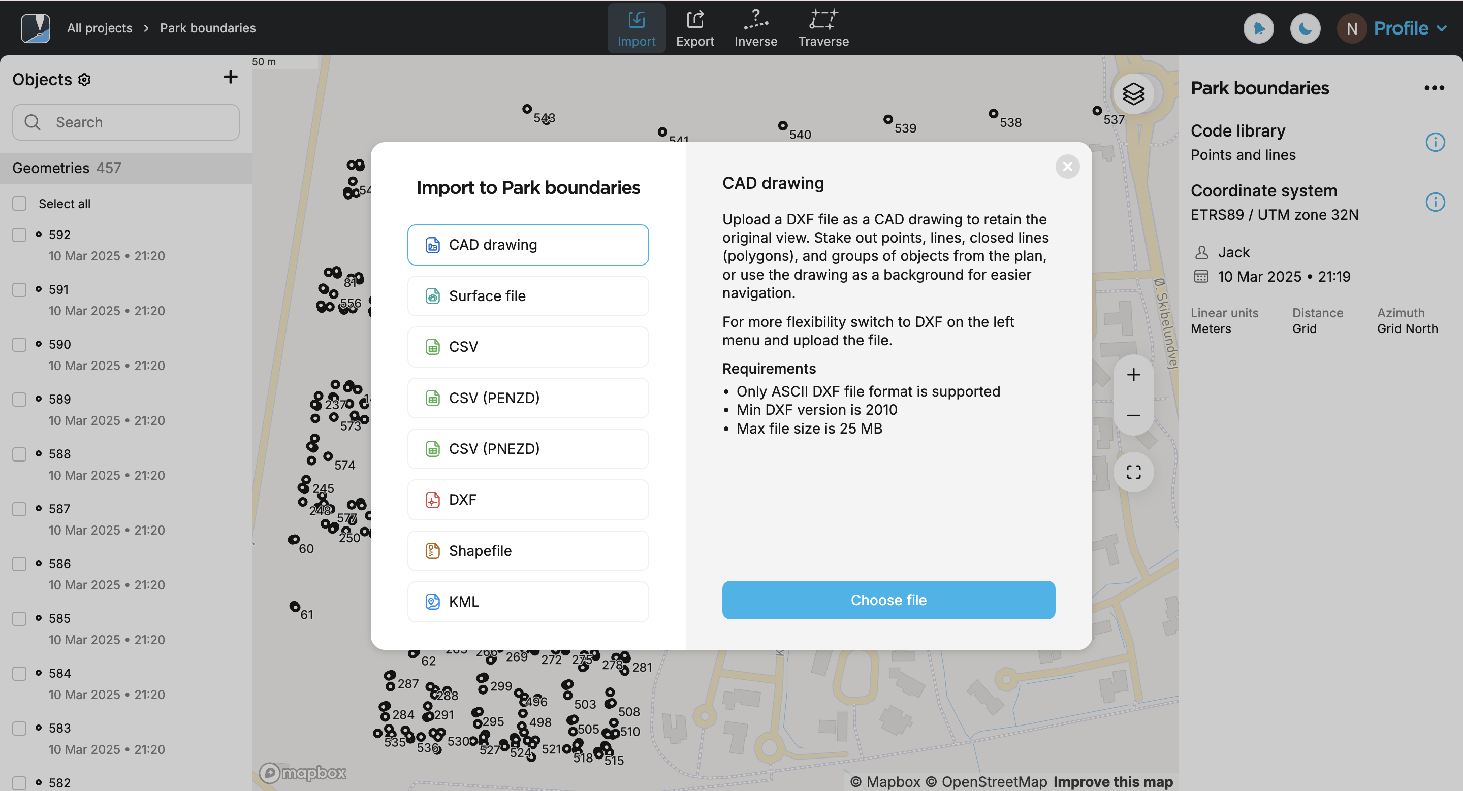
Clique no botão Import (Importar) na parte superior da tela.
-
Selecione CAD drawing (Desenho CAD) e clique em Choose file (Escolher arquivo).
noteVeja se você verificou os requisitos do arquivo e se o armazenamento não foi excedido.
-
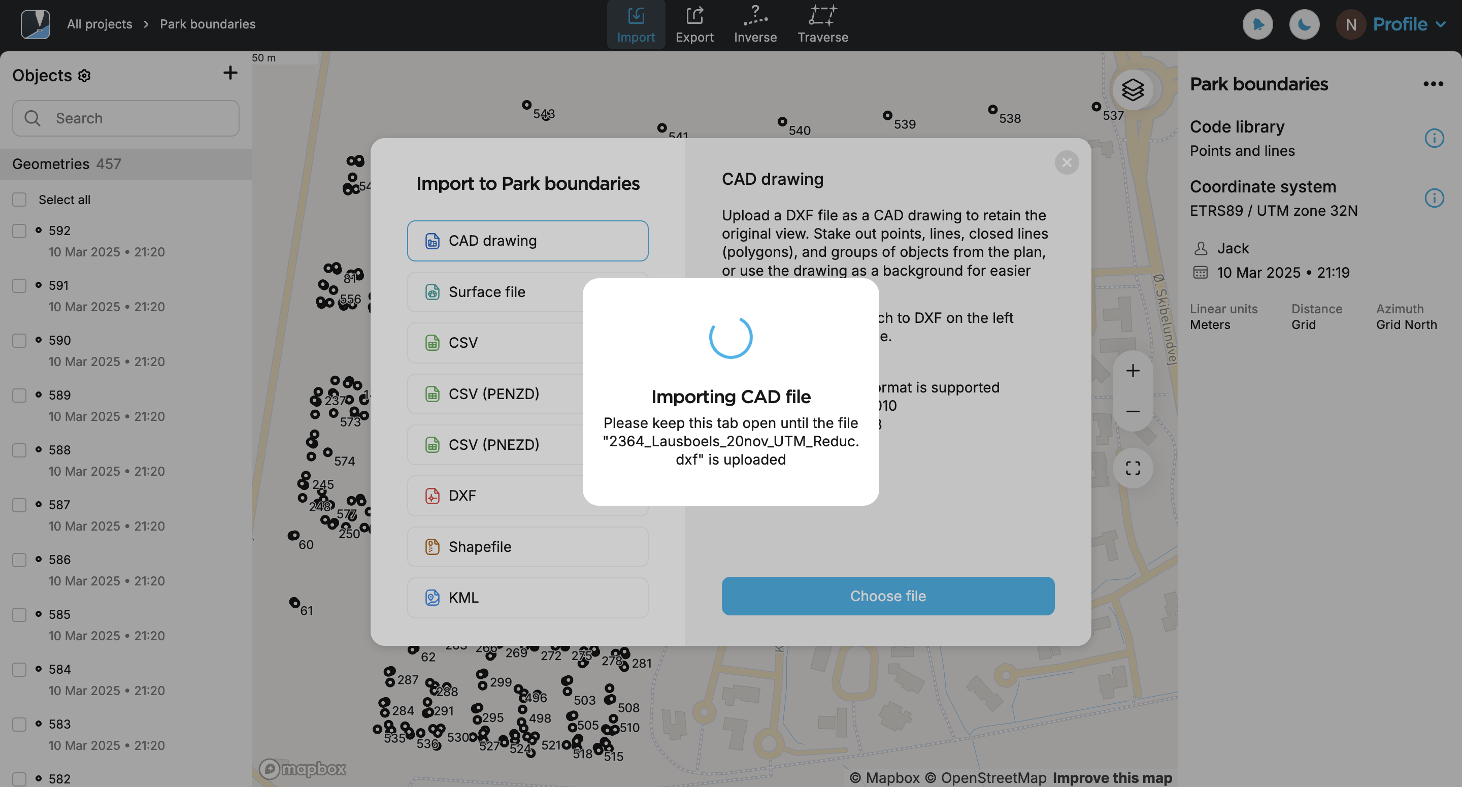
Faça upload de um arquivo no formato DXF. Seu desenho aparecerá na lista de objetos e no mapa. Por padrão, é mostrado o desenho adicionado mais recentemente da lista.
noteO desenho pode levar algum tempo para aparecer no mapa. Se ele não for totalmente convertido ou aparecer apenas parcialmente, tente dar zoom no mapa.
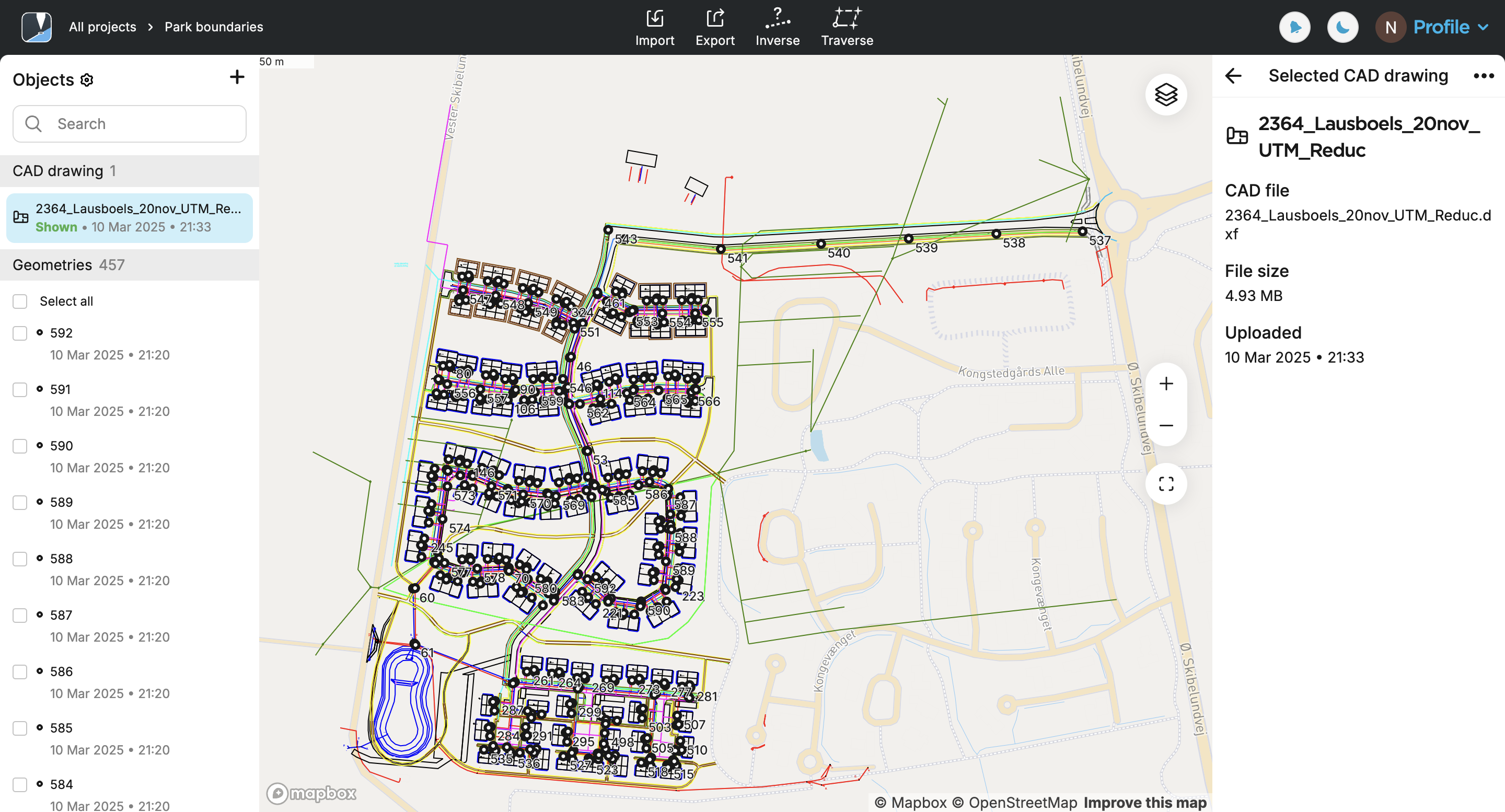
Agora, você pode acessar seu desenho CAD no aplicativo Emlid Flow.
Acesso ao desenho CAD no Emlid Flow
Depois de carregar o desenho CAD em seu projeto no Emlid Flow 360, os dados serão sincronizados e o desenho aparecerá automaticamente na lista de objetos no aplicativo Emlid Flow.
Antes de começar a fazer a locação dos objetos, certifique-se de que o rover Reach tenha uma conexão RTK estabelecida e o status FIX.
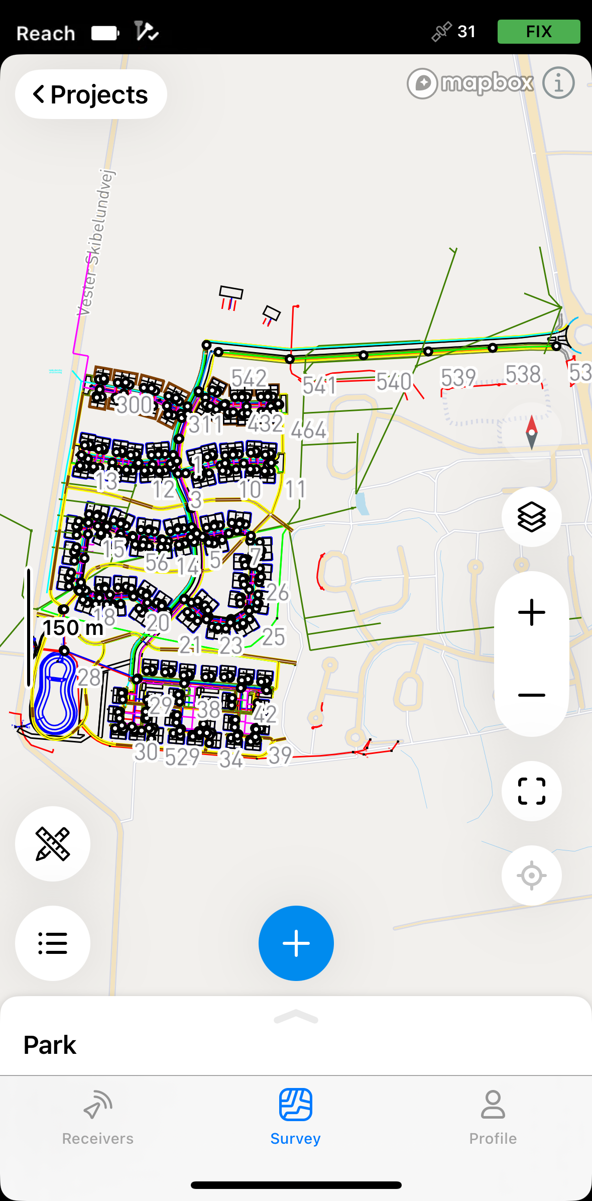
As geometrias estão disponíveis para locação somente quando o desenho CAD está ativo. Para ativar ou ocultar um desenho da lista de objetos, toque no ícone do olho.
As geometrias curvas, como círculos ou arcos, são convertidas em polilinhas.
Para a locação, siga os fluxos de trabalho abaixo, dependendo do tipo de geometria.
Locação de pontos, vértices de linhas e referências de blocos
A ferramenta de locação tem dois modos que você pode escolher ao navegar até o ponto que deseja locar:
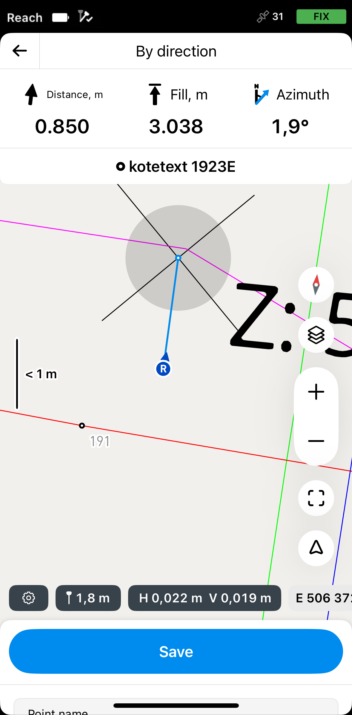
Por direção
Nesse modo, o rover está sempre centralizado no mapa, e o mapa gira de modo que a direção seja sempre para frente. A placa de locação mostra a distância e apresenta o azimute, que indica a direção do rover até o ponto projetado em uma linha. Esse é o modo padrão e é indicado pela seta no botão Mode no canto inferior direito da tela.
Se estiver usando um modelo de receptor Reach diferente do Reach RS3, caminhe um pouco com ele para orientá-lo.
By distance
Nesse modo, o rover não está centralizado no mapa e a placa de locação mostra a direção separando-a em direções Norte/Sul e Leste/Oeste e as distâncias correspondentes do rover até o ponto-alvo na linha. Este modo é indicado pela linha no quadrado do botão Mode (Modo) no canto inferior direito da tela.
Para locar uma referência de bloco no desenho CAD, siga os passos abaixo:
-
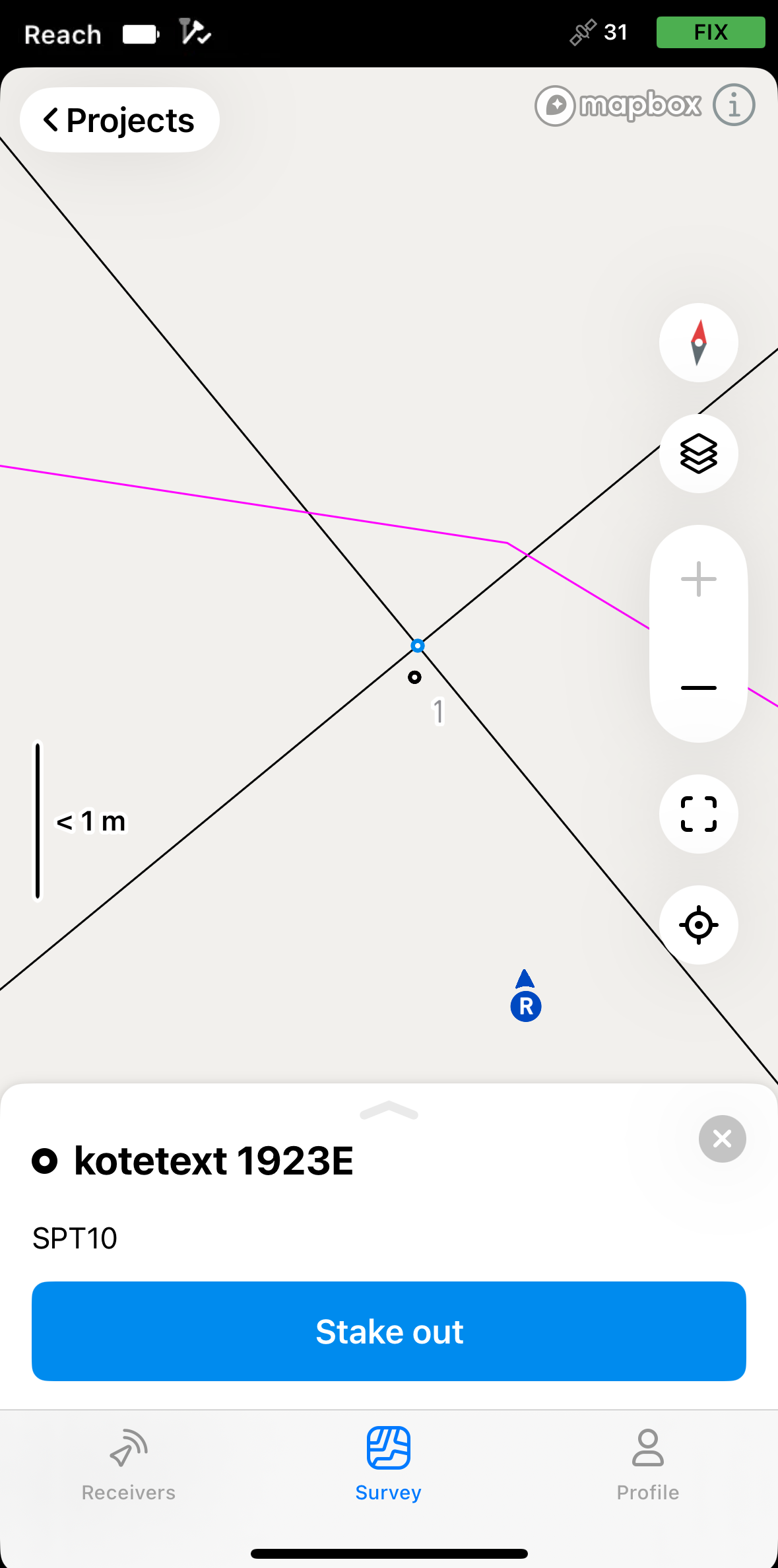
Toque na referência do bloco que você deseja locar no mapa. Você verá o ponto central destacado em azul.
noteAs geometrias de desenho CAD só podem ser acessadas pelo mapa.
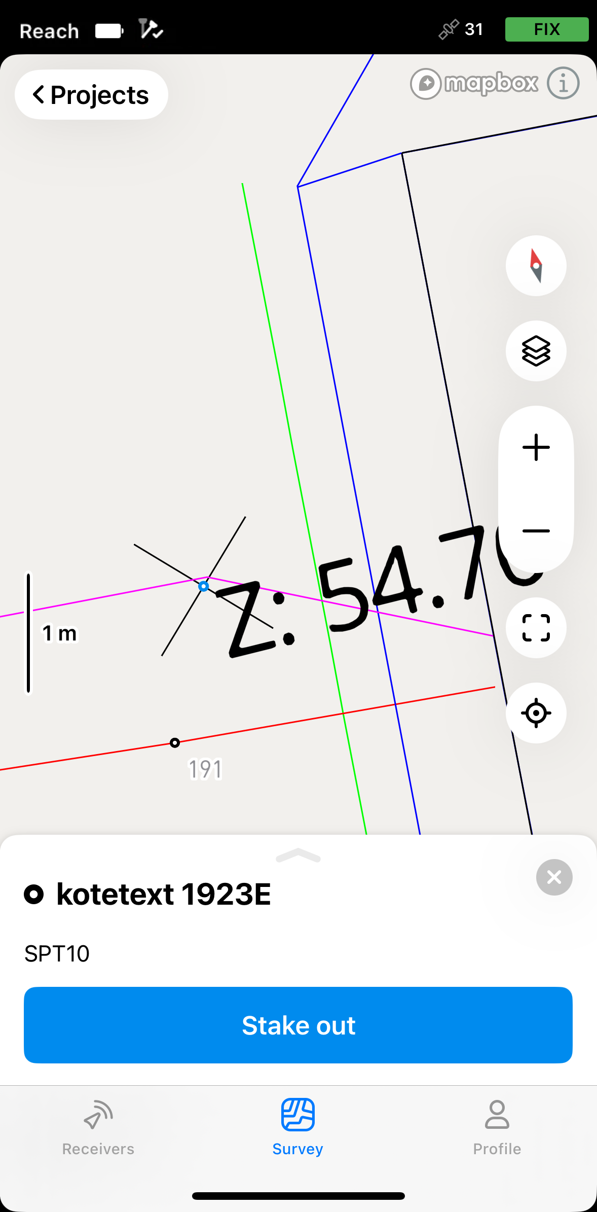
-
Toque no botão Locação.
-
Mova seu Reach na direção do ponto. Quando você se aproxima, o mapa aumenta automaticamente o zoom.
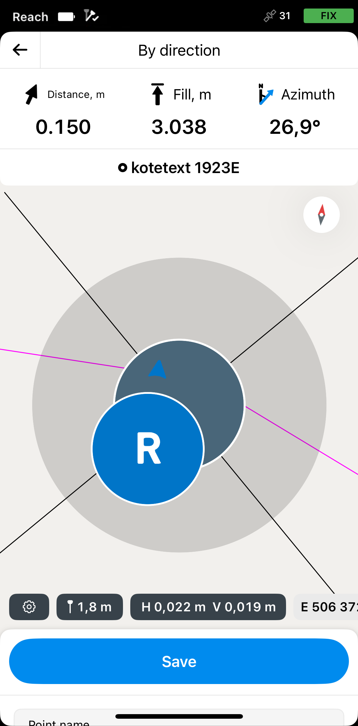 note
noteAs setas de direção na placa de locação podem ajudar você a navegar até ao ponto.
-
Mova seu Reach de modo que o alvo fique verde, mostrando que seu Reach está a menos de 2,5 cm (0,08 pés) do ponto que você está marcando.
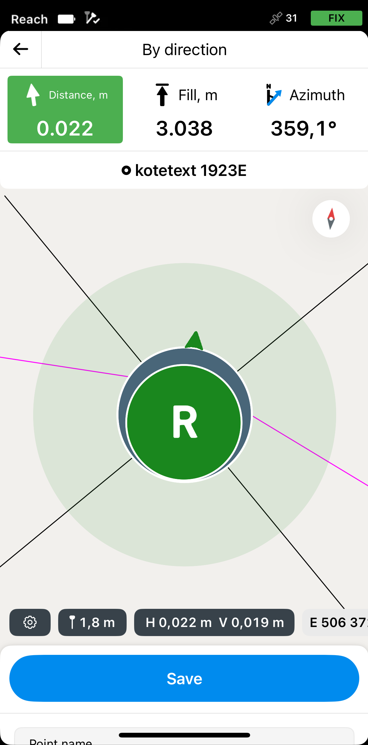 note
noteCertifique-se de que o bastão não esteja inclinado se você usar um modelo de receptor Reach diferente do Reach RS3.
-
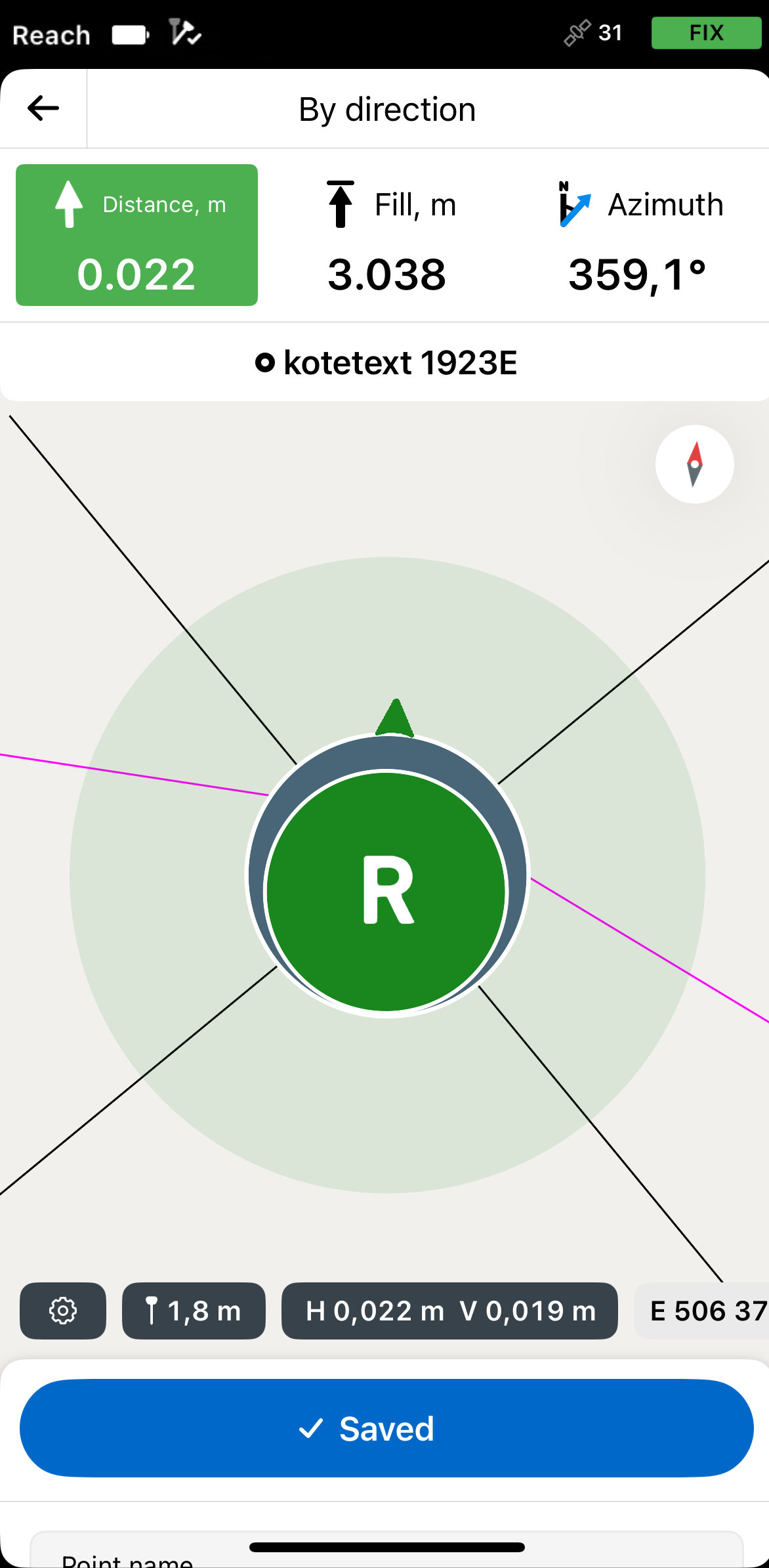
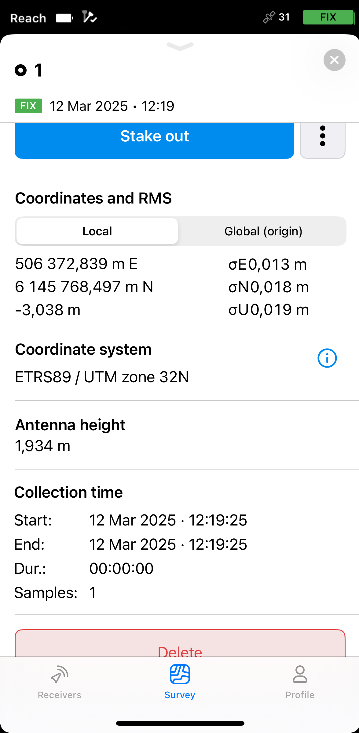
Toque em Salvar. O ponto salvo aparecerá no mapa como um ponto padrão e receberá um número ordinal. Para visualizar suas informações, toque no ponto e deslize a gaveta para cima.
noteO ponto salvo é independente do desenho CAD e é armazenado no projeto.
-
Toque no botão Voltar da placa de locação para concluir a locação da referência do bloco. Selecione outra geometria no mapa para locação e repita os passos.
Locação de linhas, polígonos e seus segmentos
O fluxo de trabalho para a locação de linhas, polígonos e seus segmentos é o mesmo. Este guia demonstra o processo usando uma linha de um desenho CAD como exemplo.
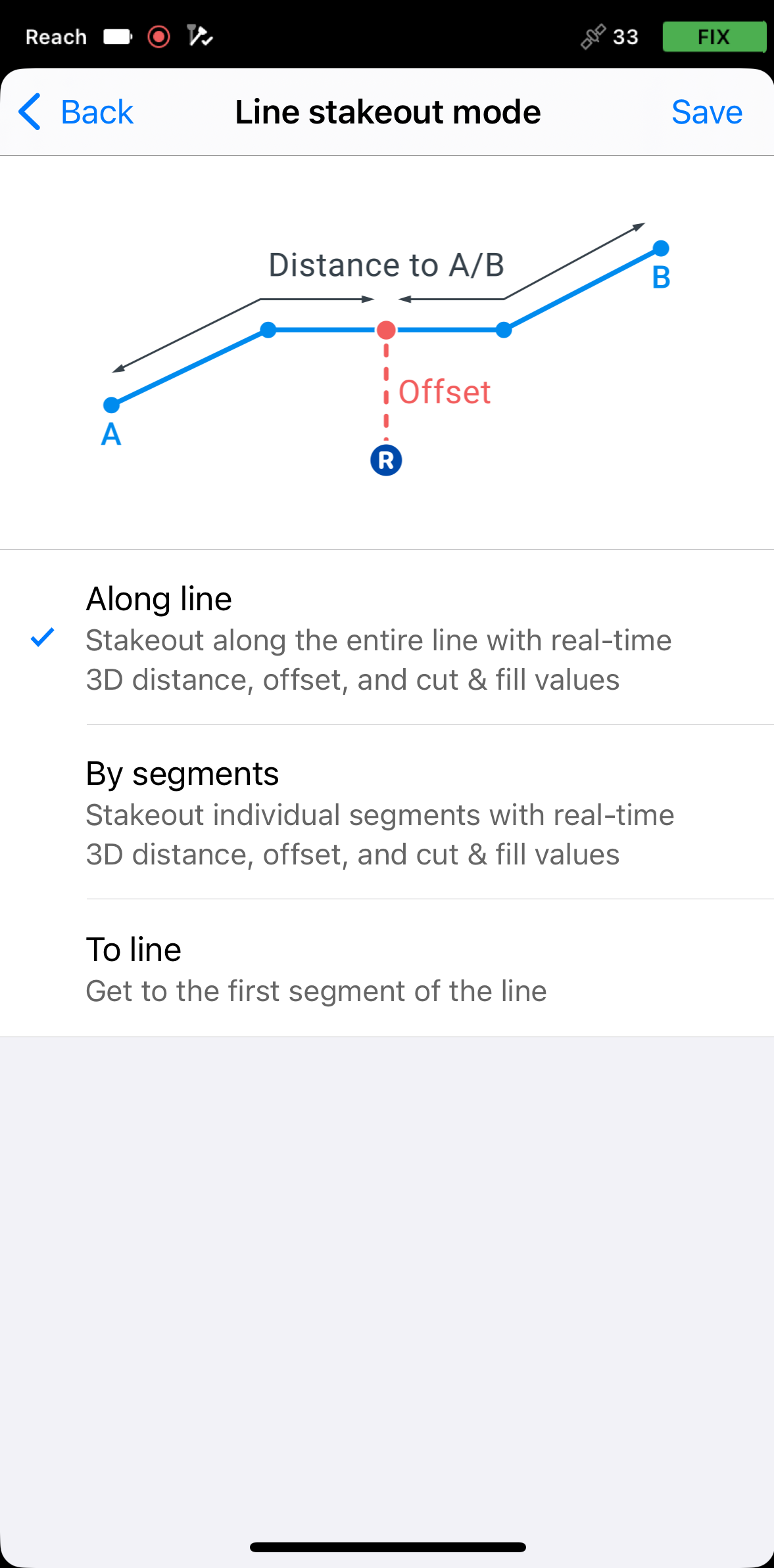
Escolha do modo de locação de linha
The Line stakeout tool has three modes:

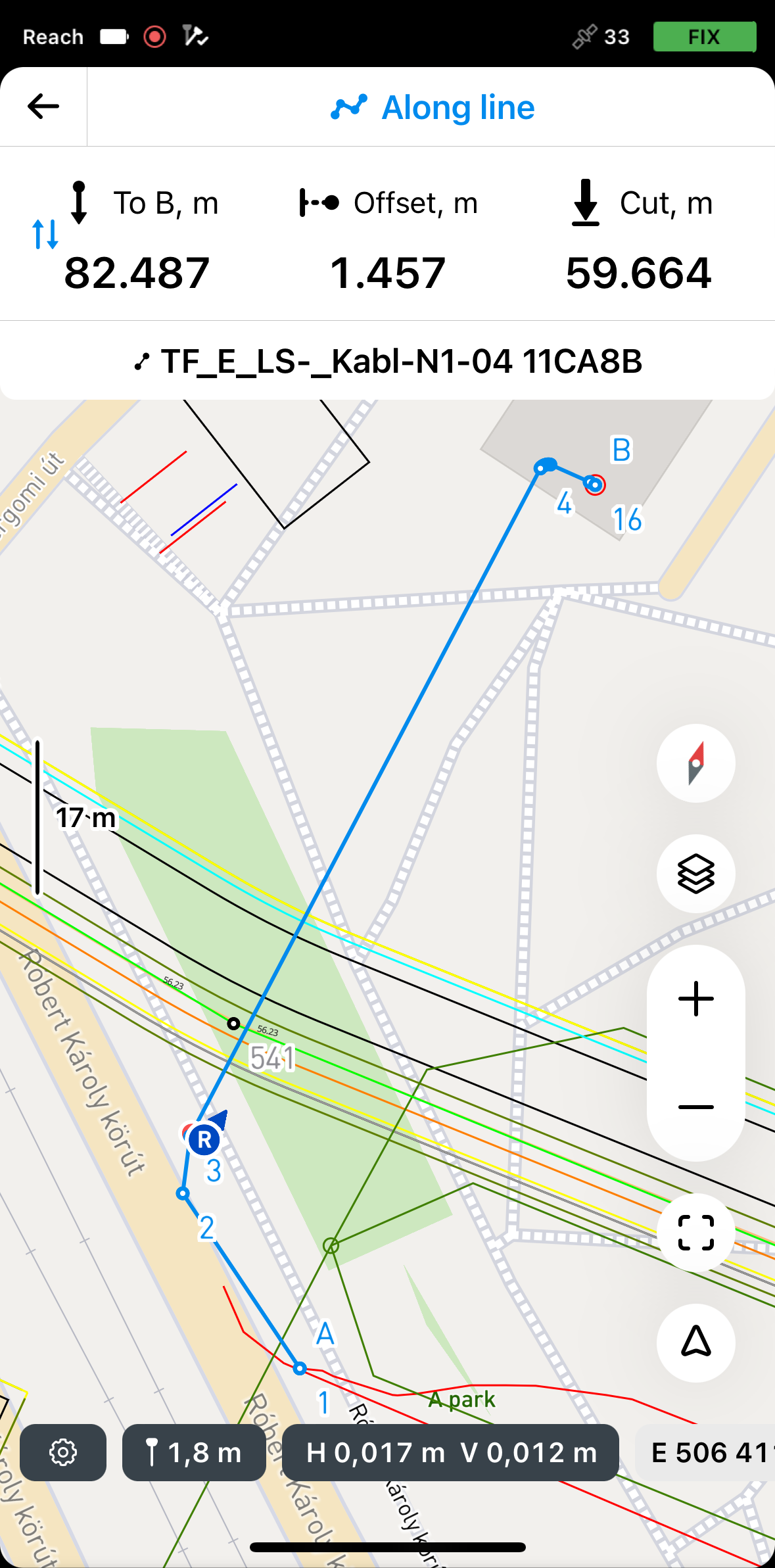
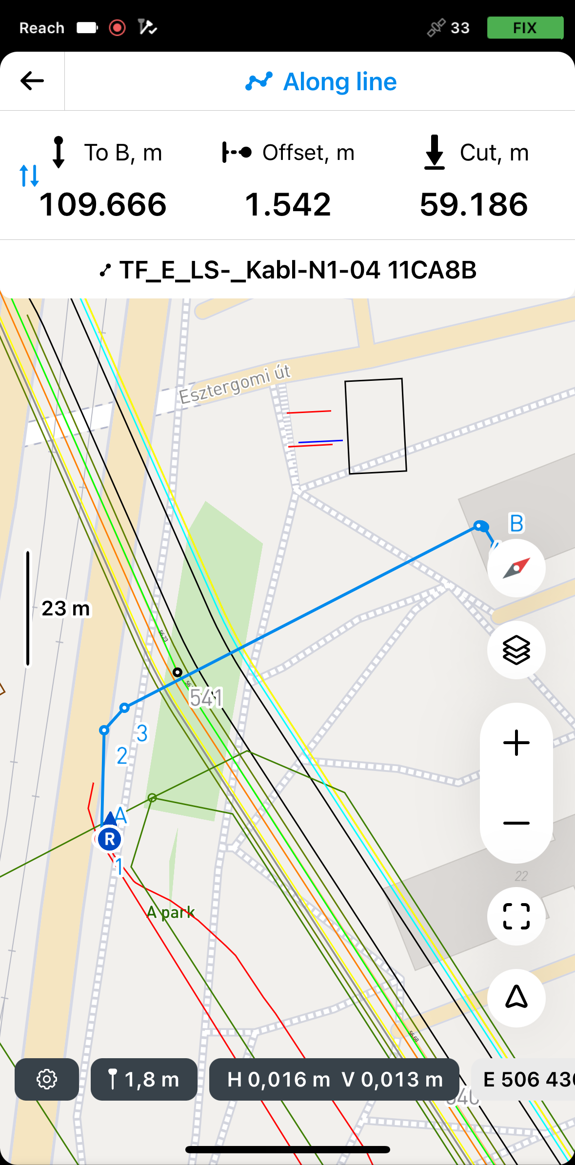
Ao longo da linha
Nesse modo, você pode locar toda a linha com distância 3D, deslocamento e valores de corte e preenchimento. Ele é ativado por padrão.
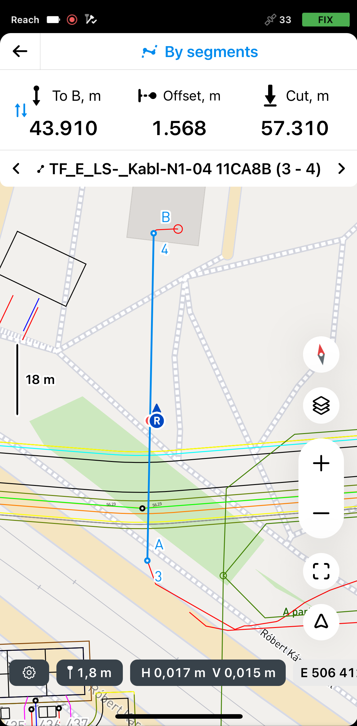
Por segmentos
Nesse modo, você pode locar segmentos individuais com distância 3D, deslocamento e valores de corte e preenchimento.
Para a linha
Nesse modo, você pode receber orientação sobre a localização de uma linha, polígono ou segmento no site. Você também pode selecionar o primeiro ponto da linha e locá-lo separadamente para alcançar a posição inicial com mais facilidade.
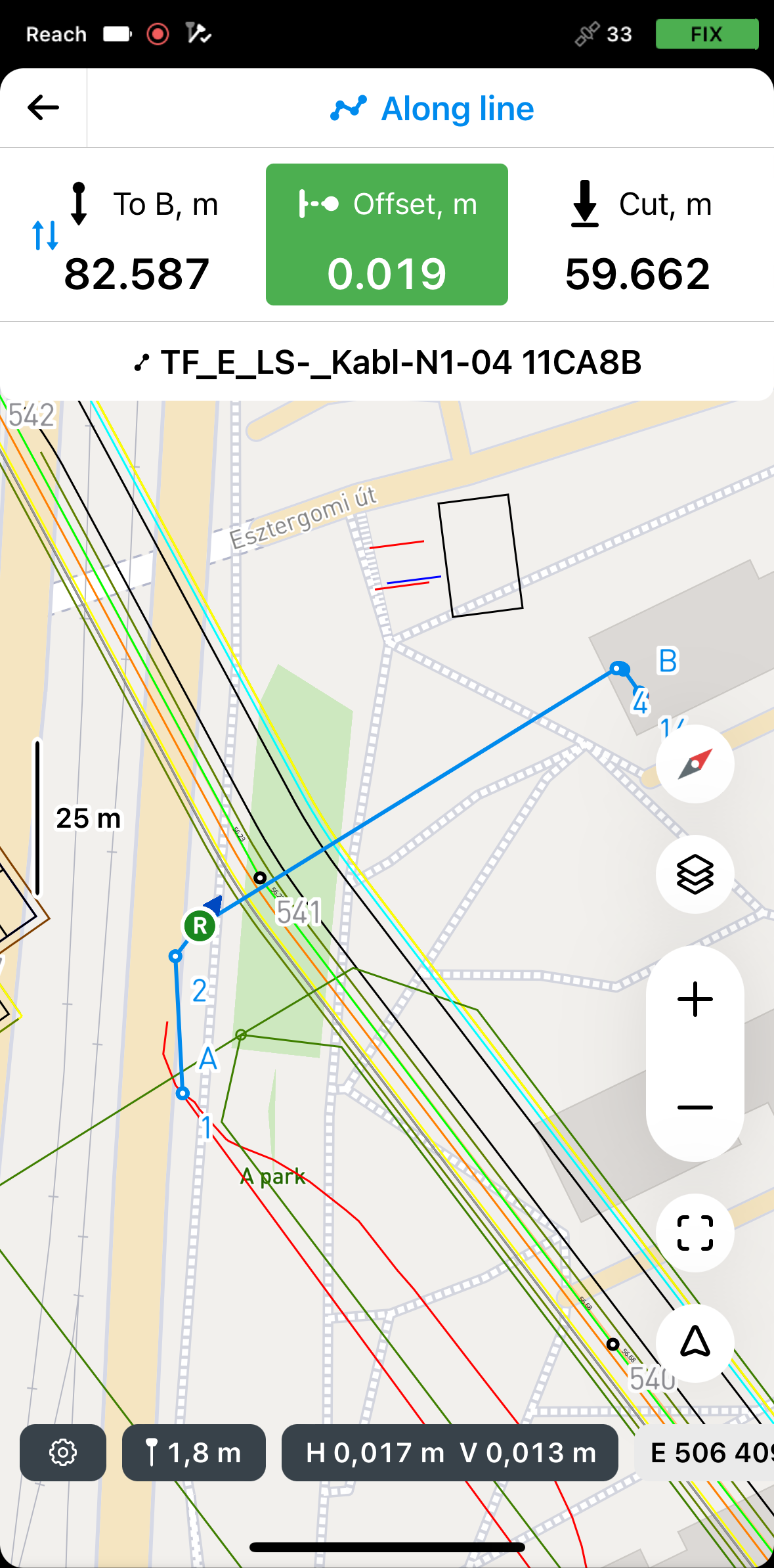
Locação de linhas usando o modo Along line (Ao longo da linha)
Para locar a linha inteira usando o modo Along line (Ao longo da linha), faça o seguinte:
-
No Emlid Flow, abra seu projeto.
-
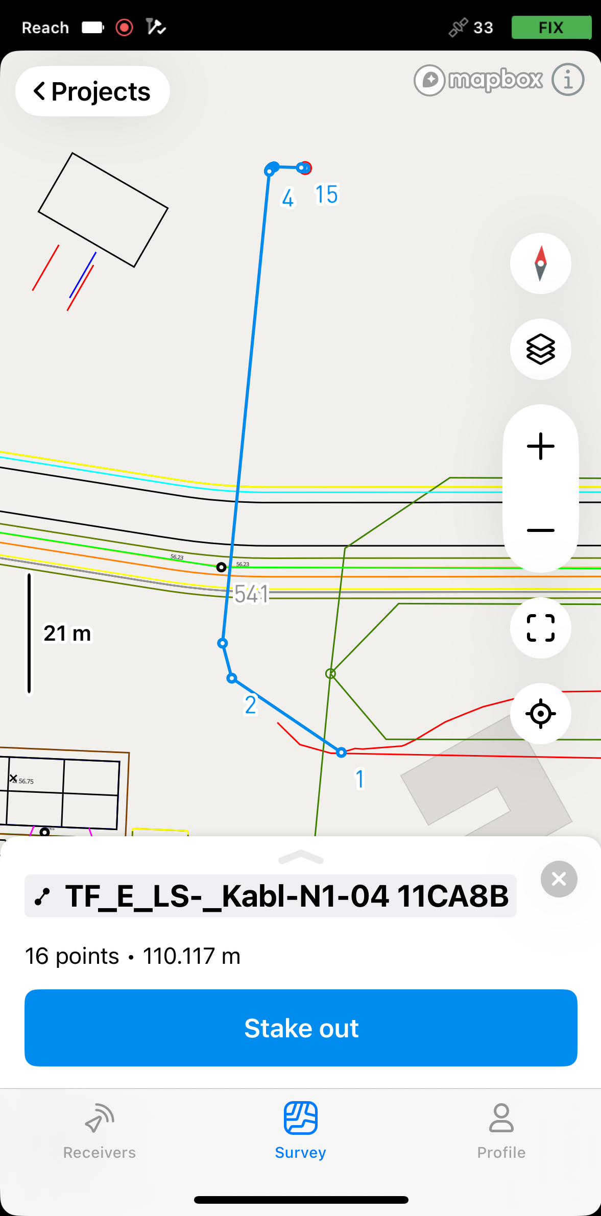
Escolha uma linha no mapa ou na lista. A linha selecionada será realçada em azul no mapa.

-
Toque no botão Locação. O modo Along line (Ao longo da linha) é aplicado por padrão. A linha receberá os rótulos A e B nos pontos inicial e final.
 note
noteO Emlid Flow lembra o último modo usado. Se você tiver usado anteriormente a ferramenta de locação de linha e um modo diferente estiver ativo, toque na parte superior da placa de locação ou nas configurações de levantamento para acessar o menu com todos os modos disponíveis e, em seguida, selecione Along line (Ao longo da linha).
-
Toque na seção To B (Para B) para escolher o final da linha a partir da qual a vigilância começará.
Agora, você pode fazer a locação diretamente sobre a linha ou locá-la com o deslocamento:
Locação sobre a linha
Para fazer a locação sobre a linha, faça o seguinte:
-
Mova o Reach de modo que a seção Offset fique verde, mostrando que o Reach está a menos de 2,5 cm (0,08 pés) de distância da linha que você está locando.
 note
noteCertifique-se de que o bastão não esteja inclinado se você usar um modelo de receptor Reach diferente do Reach RS3.
-
Observando a seção Offset (Deslocamento), verifique se a linha está definida de acordo com o projeto.
tipVocê também pode locar uma linha com encadeamento observando a seção To A (Para A) ou To B (Para B).
-
Observando a seção Cut & Fill (Corte e preenchimento), verifique o valor da altura, se necessário.
-
Para concluir a locação da linha, toque no botão Voltar na placa Locação.
Locação com deslocamento em relação à linha de referência
-
Posicione seu Reach na distância necessária da linha.
 tip
tipA seção da placa de deslocamento fica verde quando o Reach está a menos de 2,5 cm (0,08 pés) de distância da linha que você está locando.
-
Observando a placa Offset (Deslocamento), continue locando a linha.
-
Observando a seção Cut & Fill (Corte e preenchimento), verifique o valor da altura, se necessário.
Quando terminar de fazer a locação da linha, você pode tocar em outra linha no mapa para iniciar uma nova locação ou tocar no botão Voltar para sair da ferramenta de locação de linha.
Locação de linhas usando o modo By segments (Por segmentos)
Para locar segmentos de uma linha ou polígono usando o modo By segments (Por segmentos), siga os passos abaixo:
-
No Emlid Flow, abra seu projeto.
-
Toque no botão Locação. O modo Along line (Ao longo da linha) é aplicado por padrão. O segmento receberá os rótulos A e B nos pontos inicial e final.

 note
noteO Emlid Flow lembra o último modo usado. Se você já tiver usado a ferramenta de locação de linha e um modo diferente estiver ativo, toque na placa de locação para visualizar todos os modos disponíveis.
-
Para acessar os modos, toque na placa de locação, selecione By segments (Por segmentos) e toque em Save (Salvar).

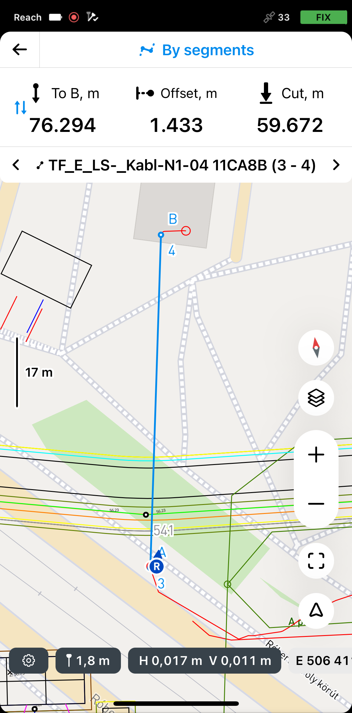
Por padrão, o processo de locação começa no segmento mais próximo. Para fazer a locação de um segmento específico, use as setas na placa de locação para navegar até o segmento desejado.
-
Toque na seção To B (Para B) para escolher o final da linha a partir da qual a locação terá início.
Agora, você pode fazer a locação diretamente sobre o segmento ou locá-lo com o deslocamento:
Locação sobre o segmento
Para fazer a locação no segmento, faça o seguinte:
- Mova o Reach de modo que a seção Offset fique verde, mostrando que o Reach está a menos de 2,5 cm (0,08 pés) de distância da linha que você está locando.
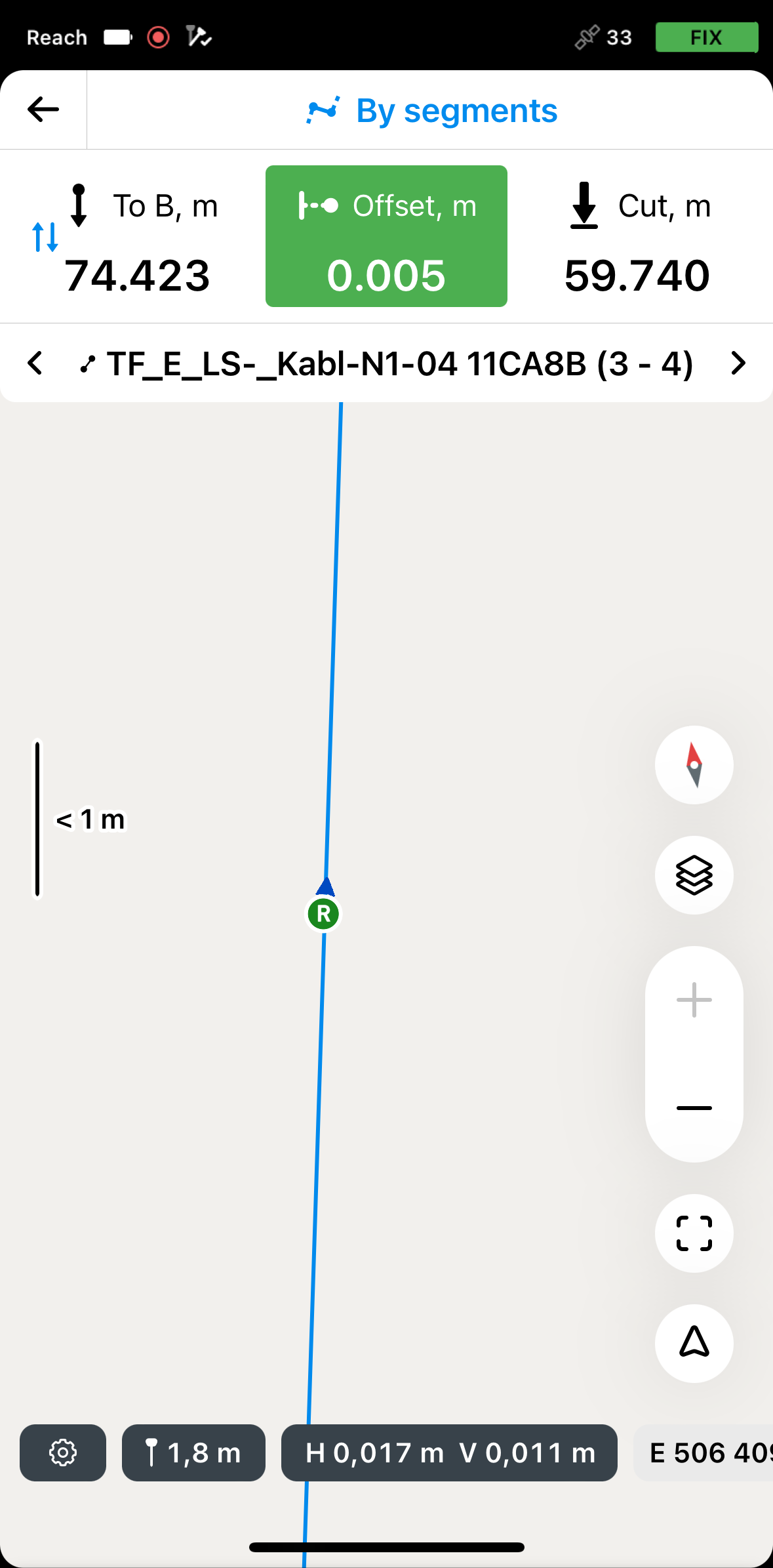
Certifique-se de que o bastão não esteja inclinado se você usar um modelo de receptor Reach diferente do Reach RS3.
-
Observando a seção Offset (Deslocamento), verifique se o segmento está definido de acordo com o projeto.
tipVocê também pode locar um segmento com encadeamento observando a seção To A (Para A) ou To B (Para B).
-
Observando a seção Cut & Fill (Corte e preenchimento), verifique o valor da altura, se necessário.
-
Mude para outro segmento que você deseja locar usando os botões de seta na placa Locação.
-
Para concluir a locação dos segmentos de uma linha ou polígono, toque no botão Voltar na placa Locação.
Locação com deslocamento em relação à linha de referência
- Posicione o Reach na distância necessária do segmento observando a seção Offset (Deslocamento).
A seção da placa de deslocamento fica verde quando o Reach está a menos de 2,5 cm (0,08 pés) de distância da linha que você está locando.
-
Observando a seção Offset (Deslocamento), continue a locar o segmento.
-
Observando a seção Cut & Fill (Corte e preenchimento), verifique o valor da altura, se necessário.
-
Quando terminar de demarcar o segmento, mude para outro segmento que deseja demarcar usando os botões de seta na placa Locação.
Quando terminar de fazer a locação dos segmentos de linha ou polígono, você pode tocar em outra linha ou polígono no mapa para iniciar uma nova locação ou tocar no botão Voltar para sair da ferramenta de locação de linha.
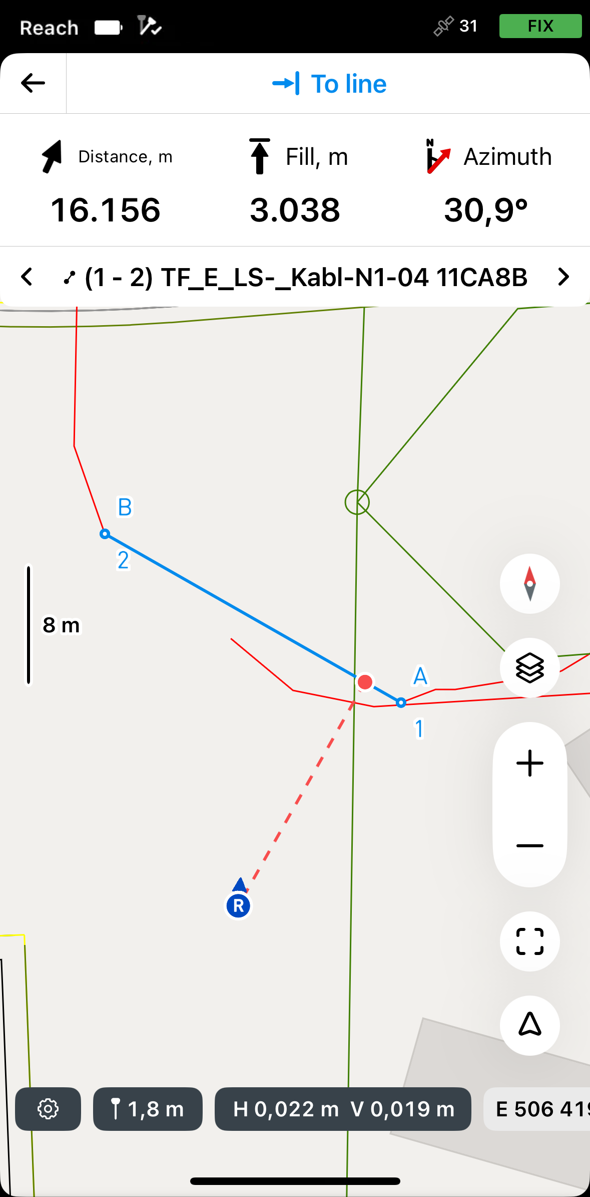
Acesso às linhas usando o modo To line (Para a linha)
O modo To line (Para a linha) é auxiliar e ajuda você a navegar até o primeiro segmento da linha. Você pode navegar até sua linha usando os seguintes modos:
Por direção
Nesse modo, o rover está sempre centralizado no mapa, e o mapa gira de modo que a direção seja sempre para frente. A placa de locação mostra a distância e apresenta o azimute, que indica a direção do rover até o ponto projetado em uma linha. Esse é o modo padrão e é indicado pela seta no botão Mode no canto inferior direito da tela.
Se estiver usando um modelo de receptor Reach diferente do Reach RS3, caminhe um pouco com ele para orientá-lo.
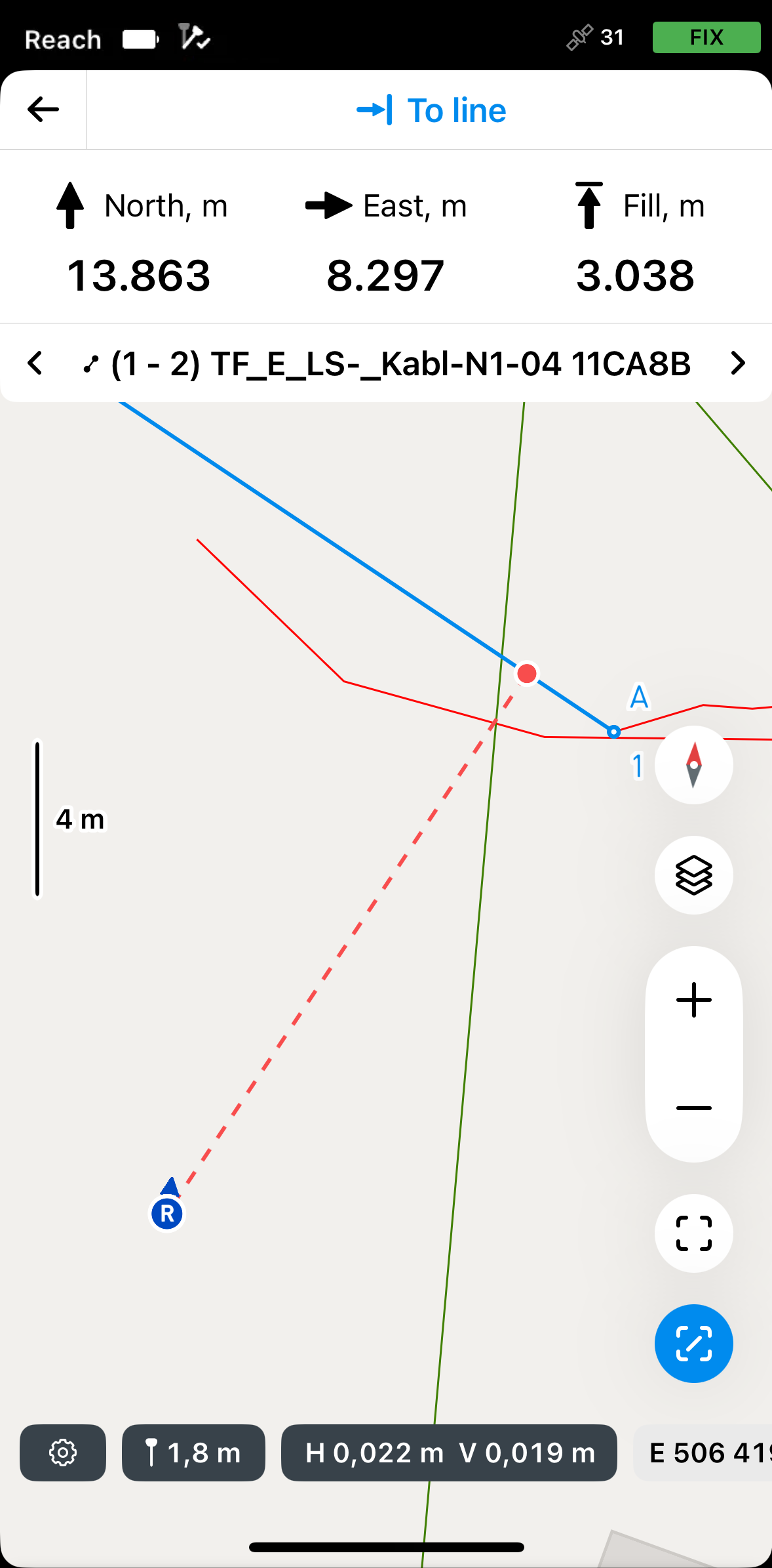
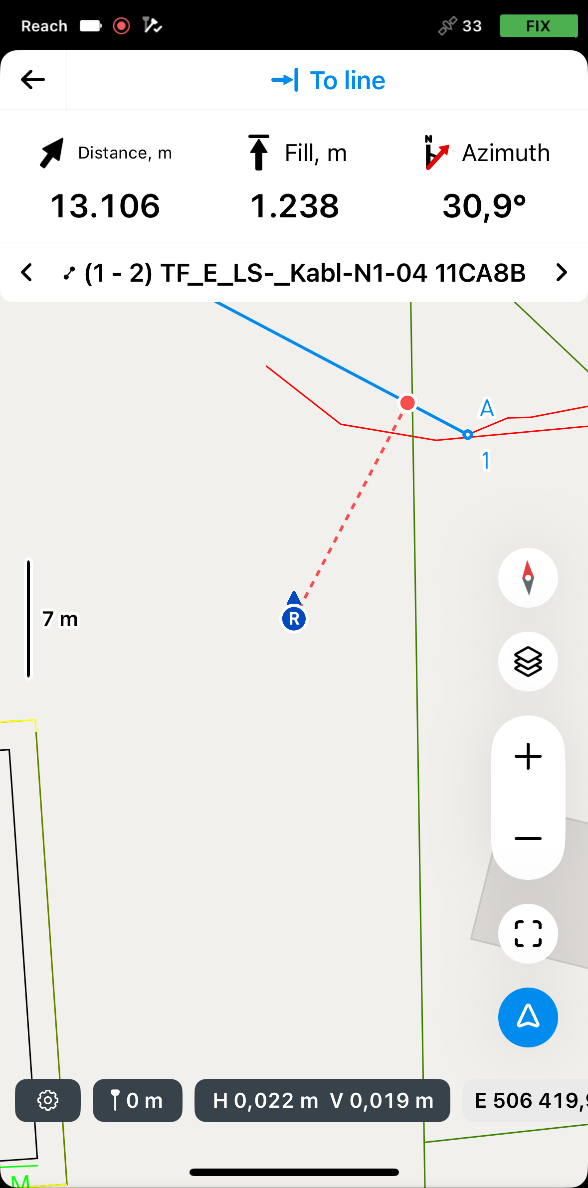
Por distância

Nesse modo, o rover não está centralizado no mapa e a placa de locação mostra a direção separando-a em direções Norte/Sul e Leste/Oeste e as distâncias correspondentes do rover até o ponto-alvo na linha. Este modo é indicado pela linha no quadrado do botão Mode (Modo) no canto inferior direito da tela.
Para ativar o modo necessário, faça o seguinte:
-
Toque no botão Mode (Modo) no canto inferior direito da tela. Ele ficará azul.
-
Para mudar para o modo desejado, toque novamente no botão Mode (Modo).
noteMover ou dar zoom no mapa desativará o modo By direction (Por direção). Ao mover o rover, o mapa não se moverá automaticamente.
Para navegar até a linha, faça o seguinte:
-
No Emlid Flow, abra seu projeto.
-
Escolha uma linha no mapa ou na lista. A linha selecionada será realçada em azul no mapa.
-
Toque no botão Locação. O modo Along line (Ao longo da linha) é aplicado por padrão.
 note
noteO Emlid Flow lembra o último modo usado. Se você já tiver usado a ferramenta de locação de linha e um modo diferente estiver ativo, toque na placa Stakeout (Locação) para ver todos os modos disponíveis.
-
Para acessar os modos, toque na placa Stakeout (Locação), selecione To line (Para a linha) e toque em Save (Salvar).
-
Mova seu Reach de modo que a seção Distância fique verde, indicando que seu Reach está a menos de 2,5 cm (0,08 pés) de distância da linha que você está demarcando.
 note
noteCertifique-se de que o bastão não esteja inclinado se você usar um modelo de receptor Reach diferente do Reach RS3.
Quando estiver na linha, mude para o modo Along line (Ao longo da linha) ou By segments (Por segmentos) para continuar o processo de locação.