Processing of project from Emlid Flow in TcpMDT
This tutorial shows how to create a digital terrain model (DTM), contour lines and profiles in TcpMDT using a topographic survey imported from Emlid Flow.
Summary
TcpMDT by Aplitop is a land survey software that runs on AutoCAD®, BricsCAD®, GstarCAD®, or ZWCAD® and provides tools for creating digital terrain models, profiles, volume calculations, roads, etc.
To integrate Emlid Flow data with the Aplitop TcpMDT application, you'll need the following:
- Emlid Flow v9.2+
- AutoCAD® v2007+, BricsCAD® Pro v16+, GStarCAD® Professional v2021+, or ZWCAD Professional® v2012+
- TcpMDT Standard v9.0+
Workflow
Below is one of the possible workflows, which consists of drawing the survey points, creating the digital terrain model, generating the contour lines, creating an alignment, and obtaining long and cross sections.
Importing points
-
Start TcpMDT.
-
Run
MDT9 > Points > Import. -
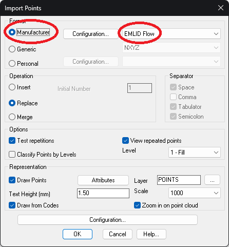
Select the Manufacturer format and choose Emlid Flow.
-
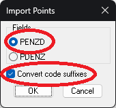
Click the Configuration button and choose the PENZD option (Point Number, East, North, Z, Description). Also leave the Convert code suffixes checked. Click OK.
-
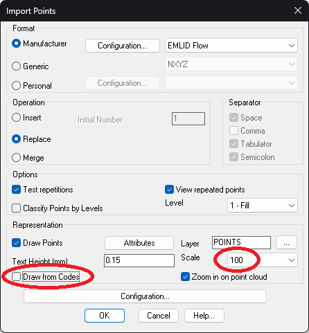
Choose a suitable scale for the representation of texts and uncheck the Draw from Codes option.
-
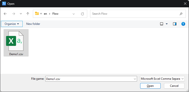
Click OK and choose the CSV file exported from Emlid Flow.
-
The points will be drawn with their numbering and elevations.
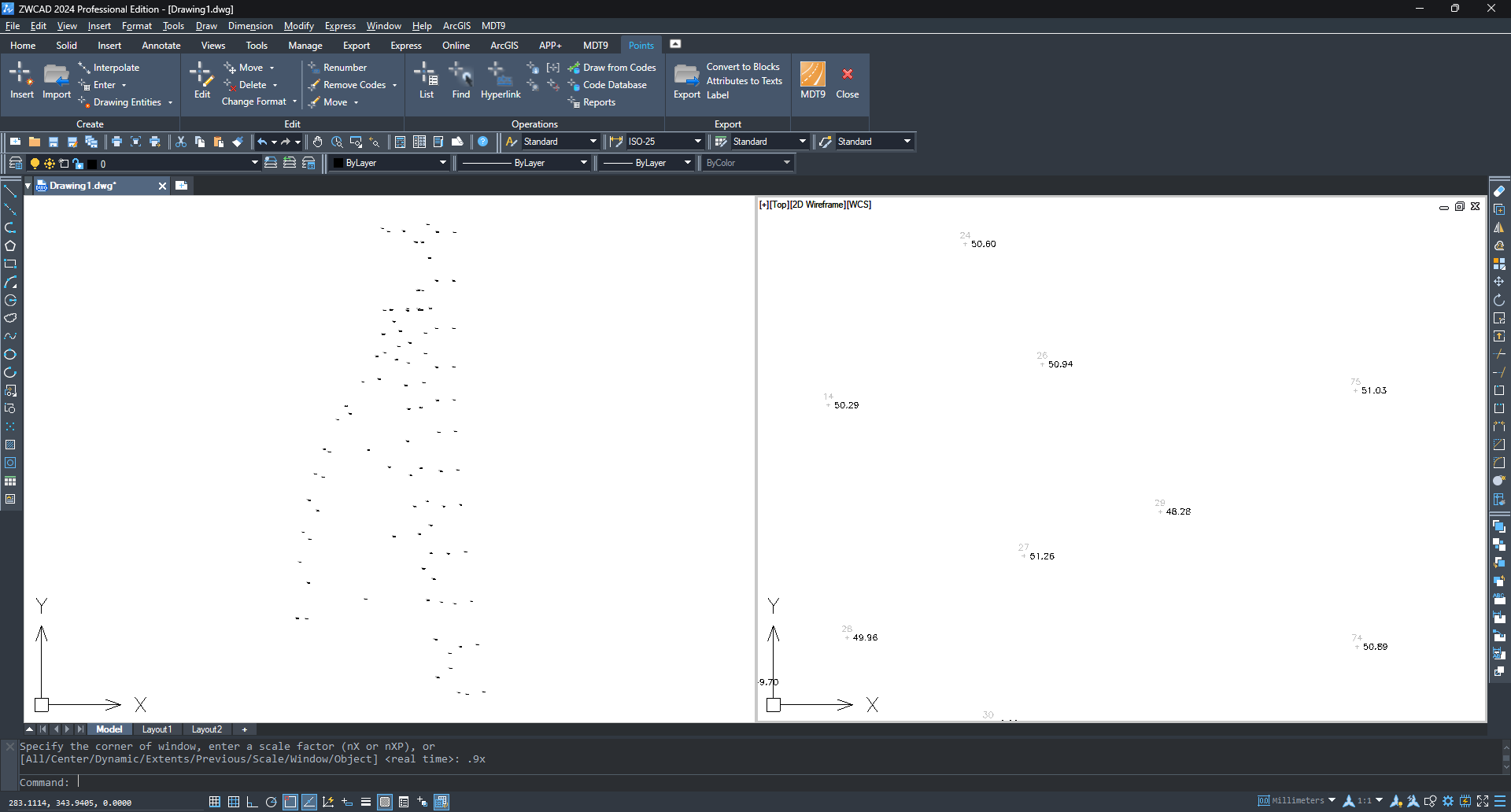
-
Run
MDT9 > Points > Listand make sure that the points in the file have been imported.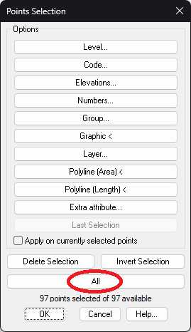
-
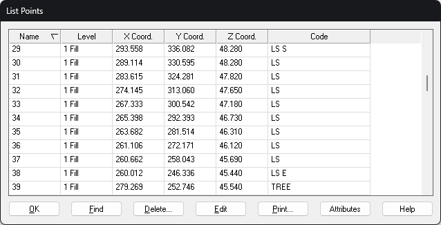
Click the All button and check that the point codes have been converted correctly. The ones with point geometry, e.g., TREE, appear as is, and the ones with the linear geometry are completed with the suffixes "S" for start and "E" for end.
Drawing break lines and blocks (Optional)
TcpMDT can generate the digital terrain model more accurately by drawing changes in the terrain slope, known as break lines. These can be drawn as polylines on different layers with CAD tools, or automatically generated if the points have been coded on the site. Blocks can also be automatically inserted from the codes, e.g. trees, manholes, posts, street furniture, etc.
-
Run
MDT9 > Points > Codes > Code Database.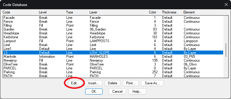
-
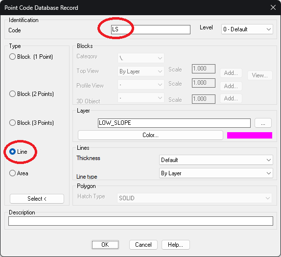
Select the item from the list to be modified and click the Edit button. The figure shows the LS code (Low Slope) which is of line type and will be drawn on the layer LOW_SLOPE in magenta color.
-
Click OK twice.
-
Run
MDT9 > Points > Codes > Draw from Codes.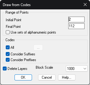
-
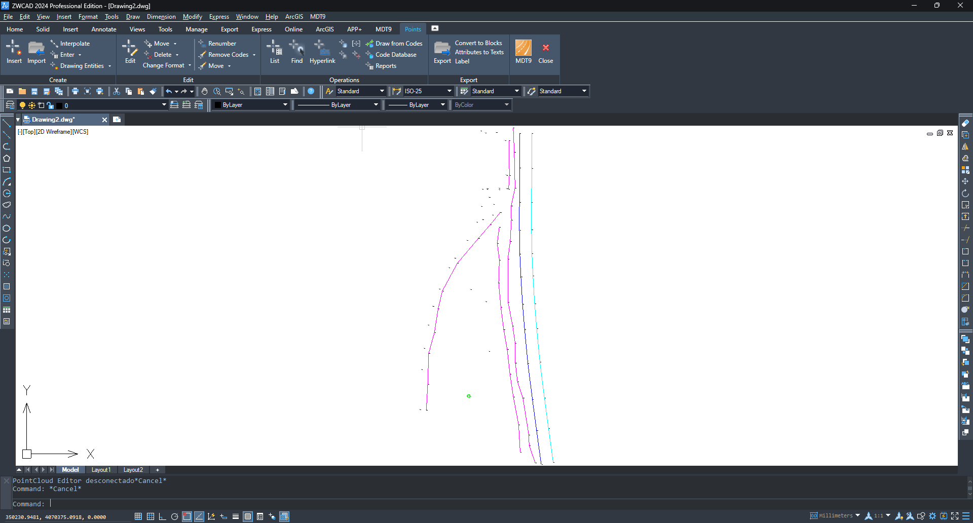
Keep the default options and click OK.
Creating digital terrain model
-
Run
MDT9 > Surfaces > Create Surfaceand accept the proposed file name. -
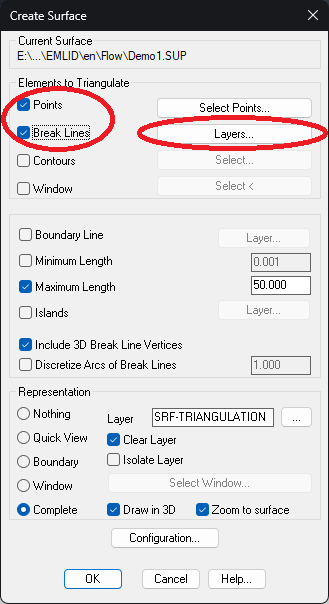
In the dialog, check that within Elements to Triangulate there are the Points and Break Lines elements. Click the Layers button.
-
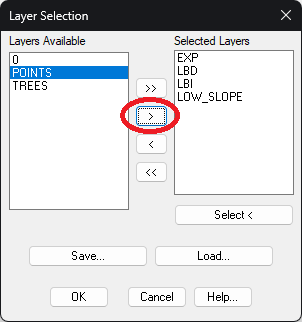
Choose the list of layers that should be considered as break lines, drawn automatically or manually, using the > button, and click OK.
-
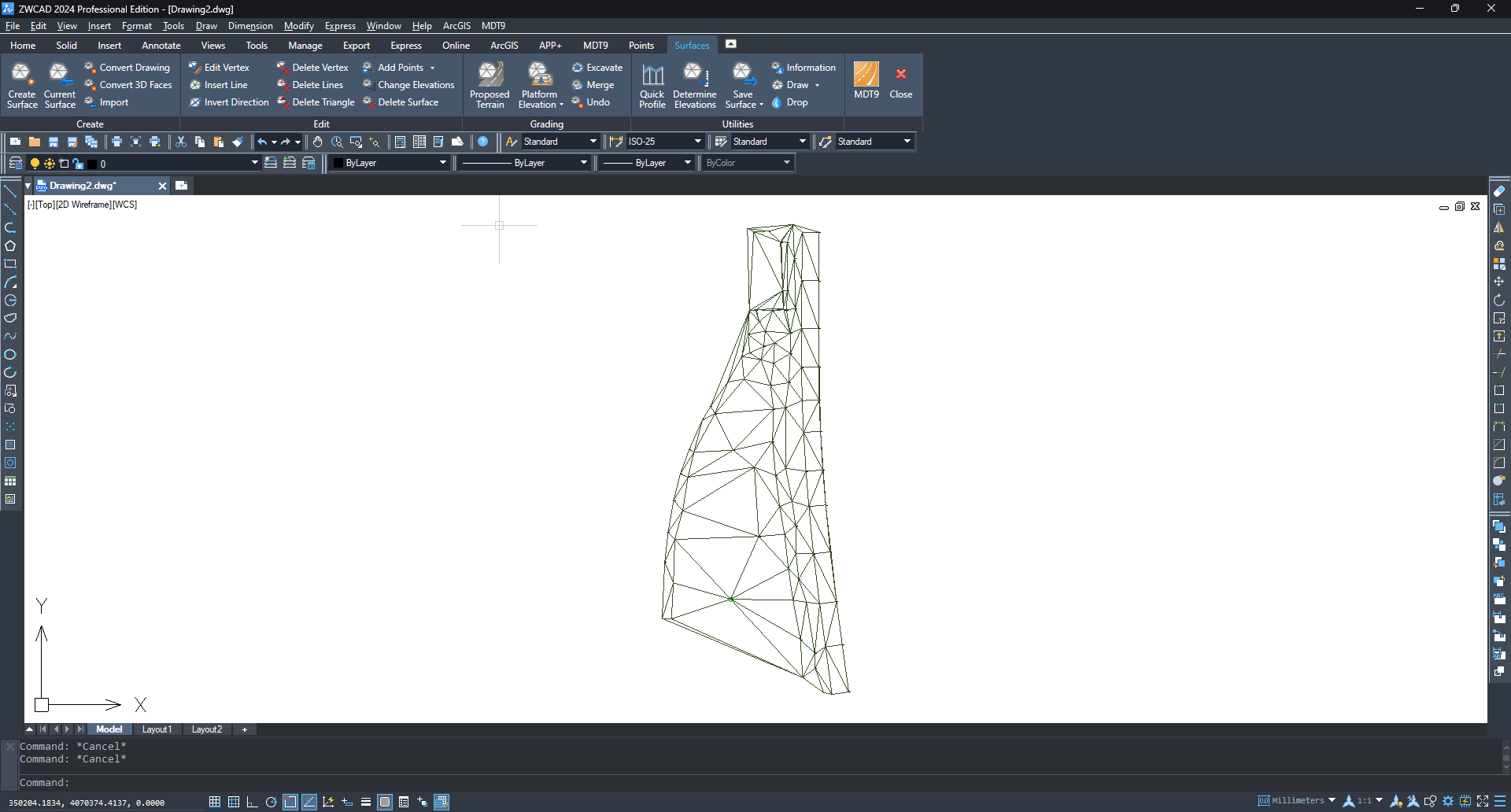
Click OK again to generate and draw the triangulation.
Generating contour lines
-
Run
MDT9 > Contour Lines/Mapping > Create Contour Lines. -
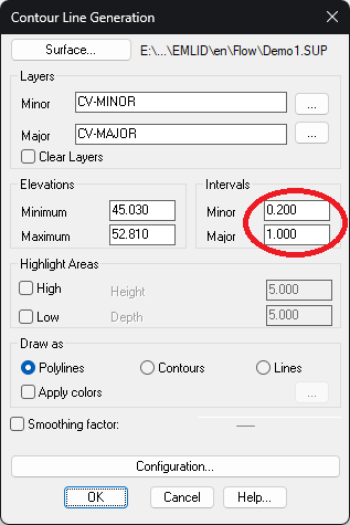
Set the intervals between minor and major contour lines.
-
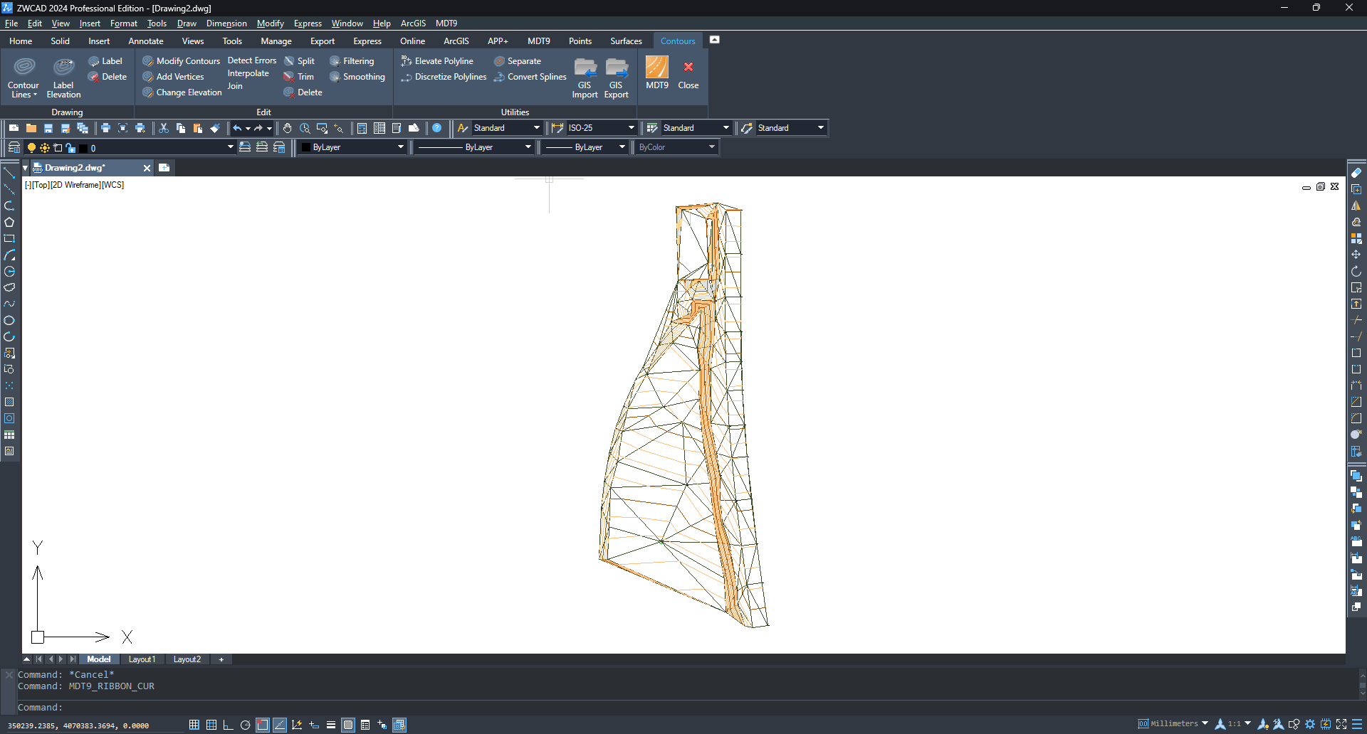
Click OK to generate the contour lines.
Creating alignment
-
Run
Draw > Polylineand draw an alignment that we'll use to create profiles.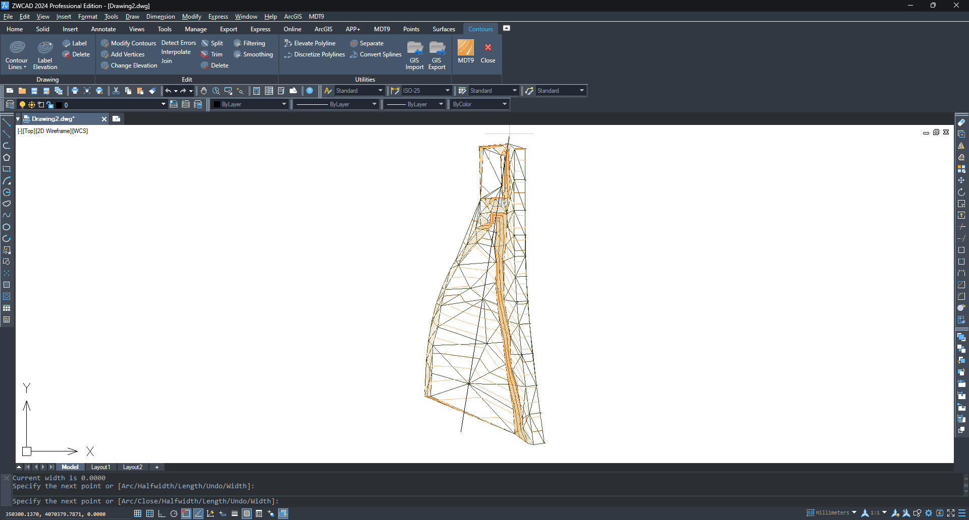
-
Run
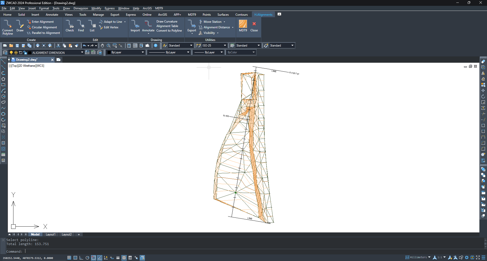
MDT9 > Horizontal Alignments > Convert Polyline to Alignmentand select the previous polyline.
-
Enable the Annotate Alignment option and click OK two times.
Creating profiles
-
Run
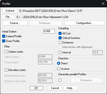
MDT9 > Long Sections > Create Long Sectionand select the alignment created in the previous step. -
In the dialog, leave all options by default and click OK.
-
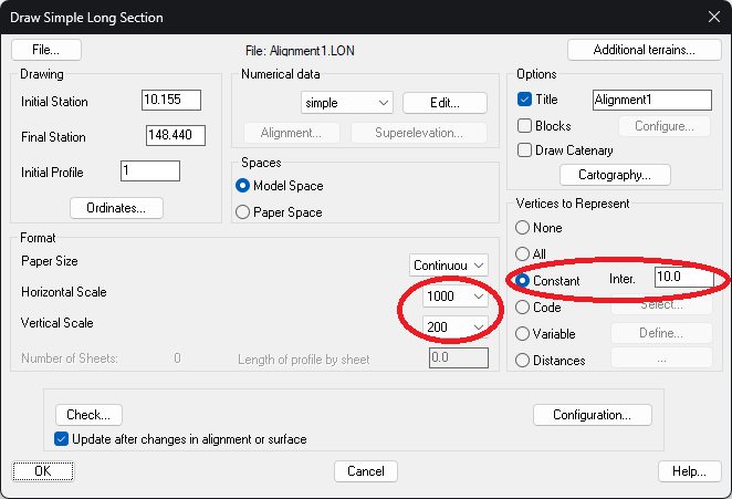
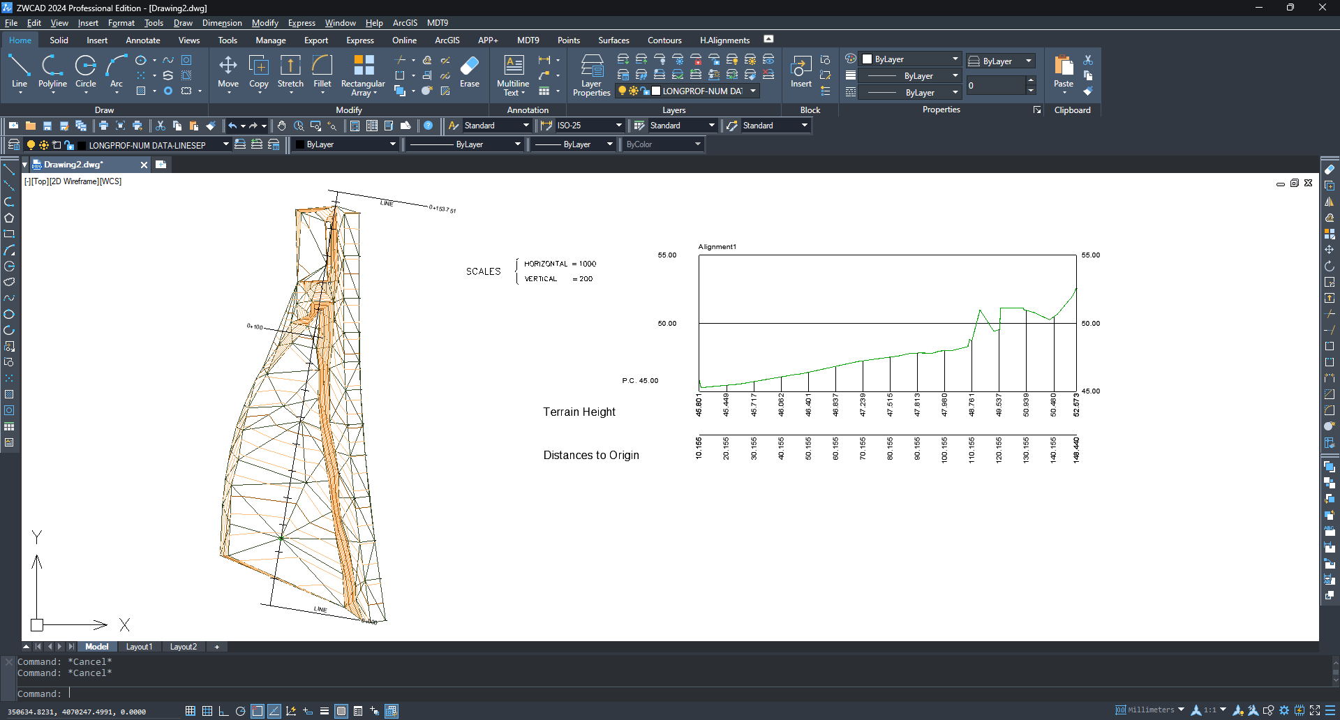
Choose the appropriate values for Horizontal Scale and Vertical Scale. In the Vertices to Represent frame, choose Constant and set an interval.
-
Click OK to draw the longitudinal profile in model space and choose an insertion point in a clear area of model space.
-
Run
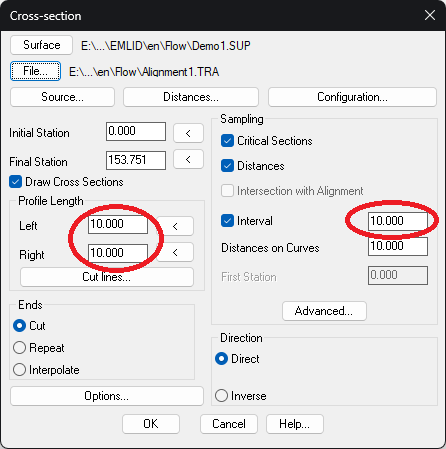
MDT9 > Cross Sections > Create Cross Sectionsand select the alignment again. -
In the dialog, set the left and right profile lengths and the interval between sections and click OK.
-
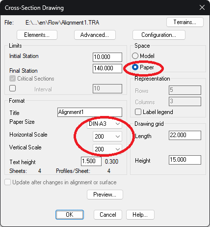
In the dialog, choose Paper Space and set the horizontal scale, vertical scale, and paper size.
-
Click OK to proceed with the drawing.