ArduPilot Integration
This guide shows how to configure Reach to send the position to ArduPilot autopilots.
Overview
Reach supports RTK-enhanced coordinates output to Navio2 and Pixhawk. To make this possible, we implemented a custom GPS protocol named ERB. If needed, you can use the industry-standard NMEA format instead.
ERB support is included to ArduPilot starting with the following versions:
- ArduCopter 3.4
- ArduPlane 3.5.0
- APMrover 3.1
You can check the ERB protocol description here.
Recommended Setup
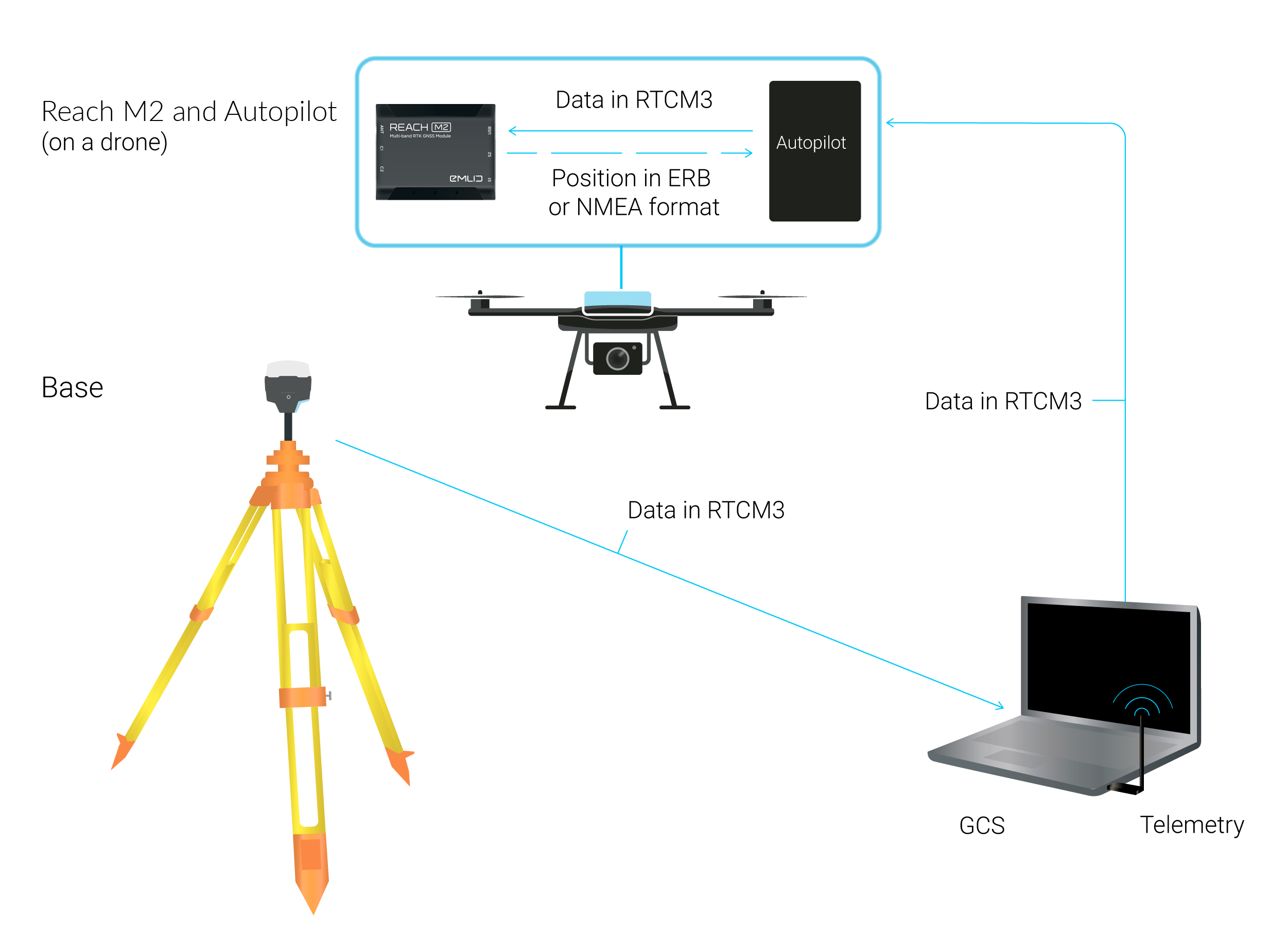
We recommend the following setup:
- Navio2, Edge, or Pixhawk with the ArduPilot firmware. It is preferable to use the last stable version.
- Base station is the Reach RS2/RS2+/RS2+ or Reach RS/RS+ unit in Wi-Fi AP mode, configured as a TCP server.
- GCS (Ground Control Station) is a laptop with Mission Planner (version 1.3.35 and higher), connected to the base Reach Wi-Fi hosted network.
- Telemetry connection that is provided via a serial radio.
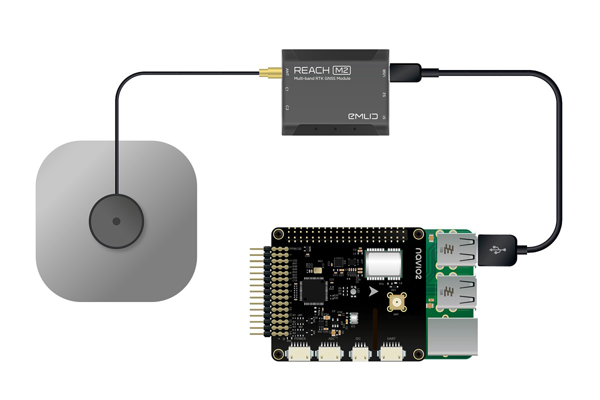
- Rover Reach M2 or Reach M+ unit is mounted on a drone and connected to Navio2 or Pixhawk via the 6P-to-6P wire. This connection type will solve three issues at once: power Reach, allow ArduPilot board to pass base corrections and allow Reach to pass RTK solution back.
The following guide will show you how to configure Navio2 or Pixhawk and Reach to work in this setup. If you want to change the workflow, it should be easy to do so, as every part of the system is independent of others.
Connect Reach to Autopilot
To pass the position data from Reach, connect it to your autopilot. You can connect your Reach to Pixhawk, Navio2, and Edge.
Connect Reach to Pixhawk
To provide RTK solution to Pixhawk, Reach needs to be connected via a serial port. You can do that by plugging the serial cable into Reach receiver's JST-GH port and Pixhawk's Serial 4/5 connector.
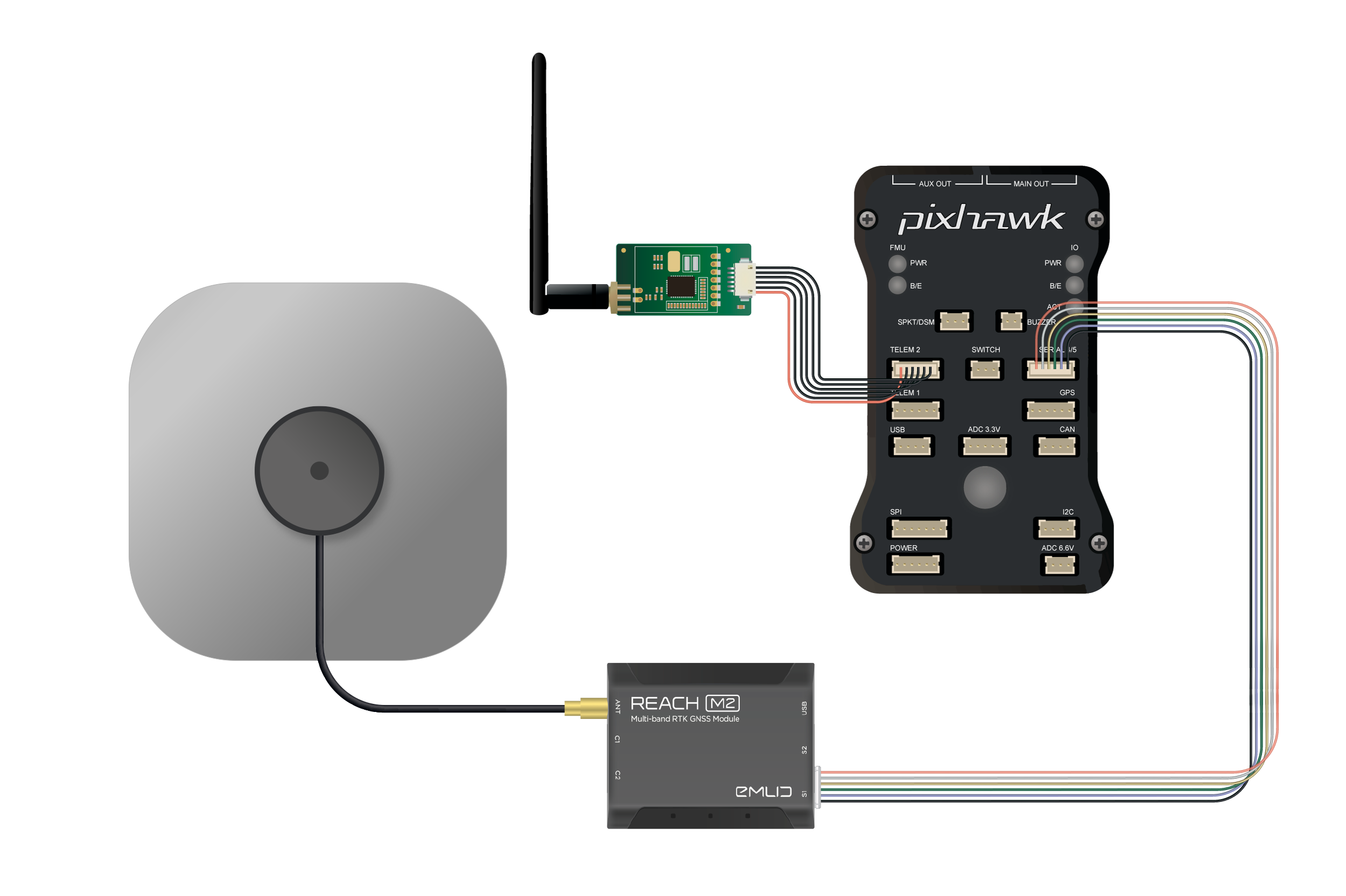
It is recommended to supply Reach from an external power source. Pixhawk may not provide enough power for Reach in some cases.
Connect Reach to Navio2
You can connect Reach receiver to Navio2 in two ways: over UART or USB. To provide Navio2 with RTK solution over UART, connect Reach receiver's JST-GH port with the UART port on Navio2.
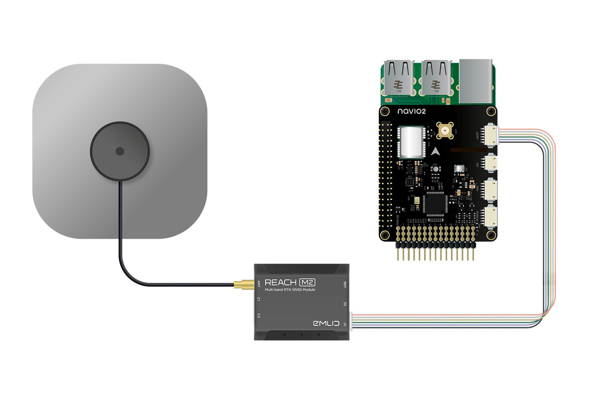
To work with USB, connect Reach receiver's Micro-USB port with a USB port on your Raspberry Pi.
Configure Reach Module to Work with ArduPilot
Set Up Your Rover
The serial connection is used to accept base corrections and send solution at the same time.
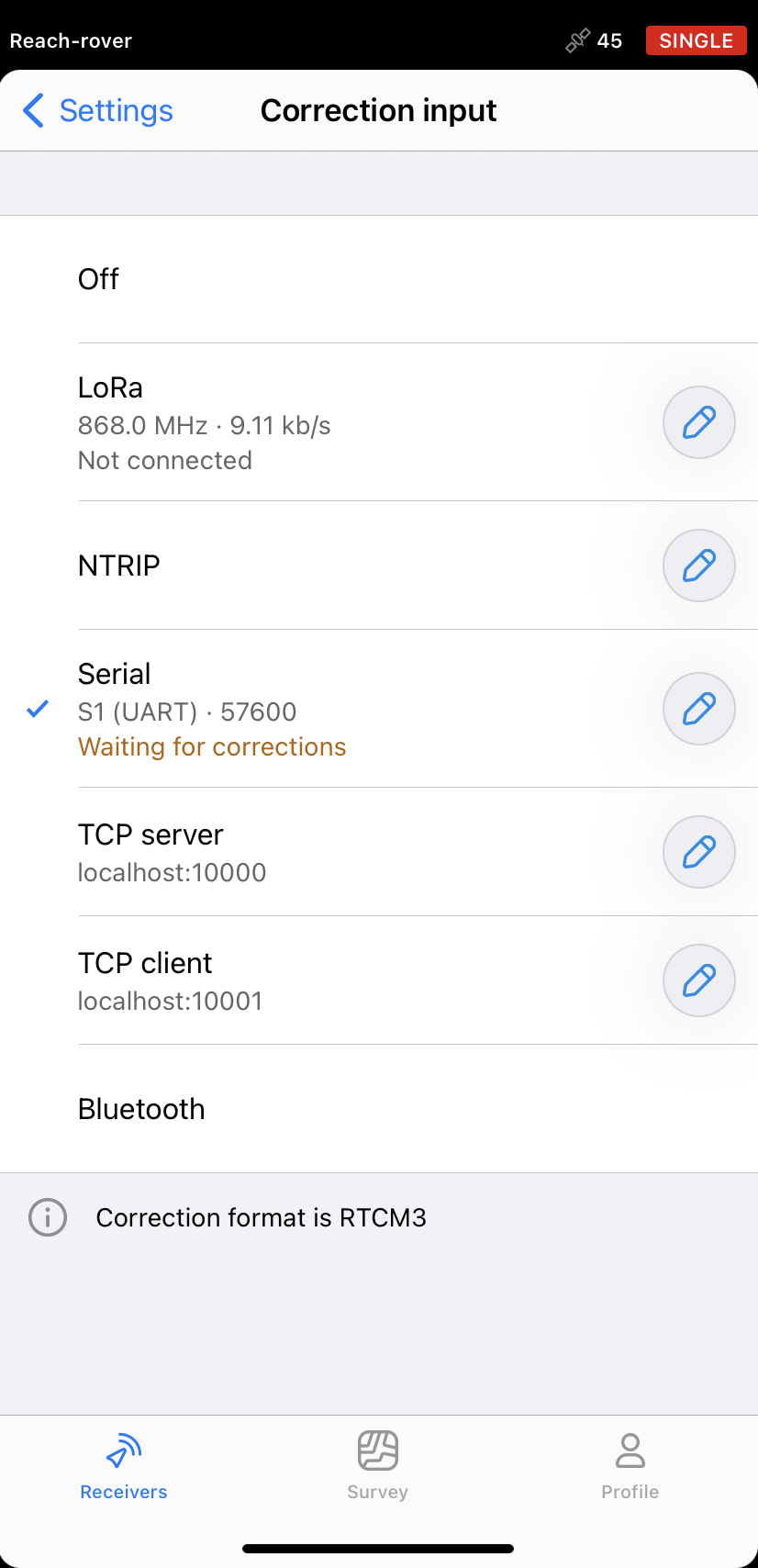
First, configure the corrections input:
-
Open Emlid Flow and connect to your rover.
-
Tap Correction input.
-
Select Serial.
-
Choose S1 (UART) or USB to PC as the port.
-
Choose the desired baud rate (57600 for default).
-
Tap Save button to save settings.
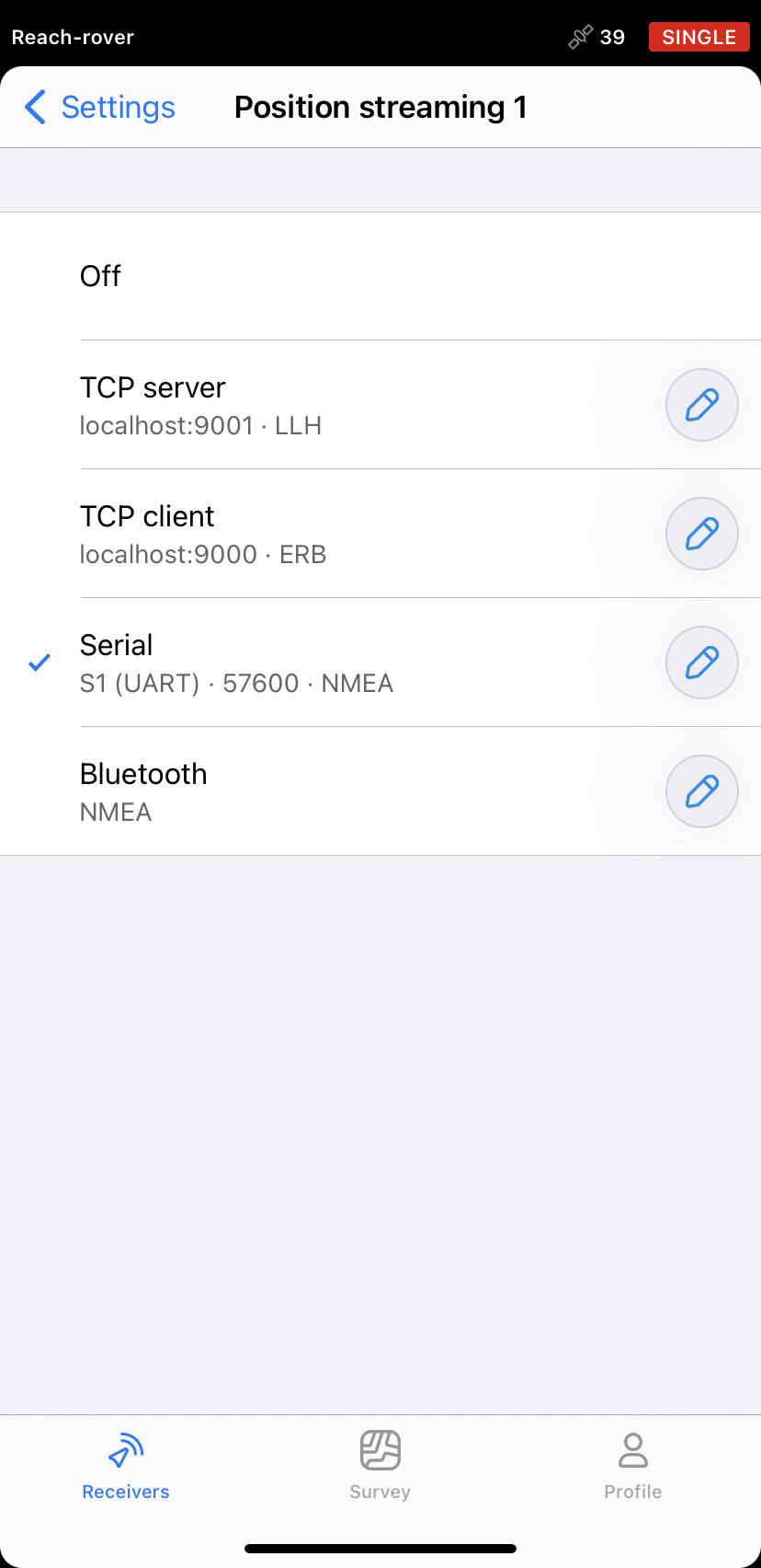
After that, configure the position streaming:
-
Return to the Receivers screen and go to Settings.
-
Tap Position streaming 1.
-
Select Serial.
-
Choose S1 (UART) or USB to PC as the port.
-
Choose the desired baud rate (57600 for default).
-
Choose NMEA or ERB as position streaming format.
-
Tap Save button to apply changes.
Set Up a Correction Link
Reach supports a number of ways to accept base corrections, including the popular in UAV area serial radios. However, having a separate radio link for base corrections only is highly ineffective. To solve this, you can use the telemetry radio as a carrier for RTK corrections. GCS can pass these corrections to the autopilot with a feature called GPS inject. This functionality is available in Mission Planner only.
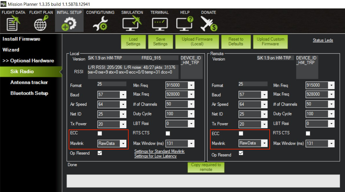
Configure Radio to Embed Corrections Into Telemetry
With default settings, radio telemetry is not optimised for sending RTK corrections. This may cause correction data delivery delays and even loss. These slips will deteriorate RTK solution quality, so you need to minimize them.
Radio configuration is done with telemetry disconnected.
To configure a radio, do the following:
Make sure MAVLink connection is disabled before changing radio settings.
-
Click INITIAL SETUP in the menu bar.
-
Go to Optional Hardware and select Sik Radio in the side menu.
-
Click Load Settings and wait for the parameters of both radios to load.
-
Uncheck the ECC field.
-
Choose RawData in the Mavlink field.
-
Click Save Settings.
Configure ArduPilot to Accept Reach Module Solution
It is recommended to use Reach as a second GPS unit only.
To launch ArduPilot on Navio2, add to your starting command one of the following arguments:
-
For UART connection:
-E /dev/ttyAMA0 -
For USB connection:
bash -E /dev/ttyACM0
This will enable to use Reach as external GPS.
ArduPilot configuration will require setting some parameters via Mission Planner. After connecting, do the following:
-
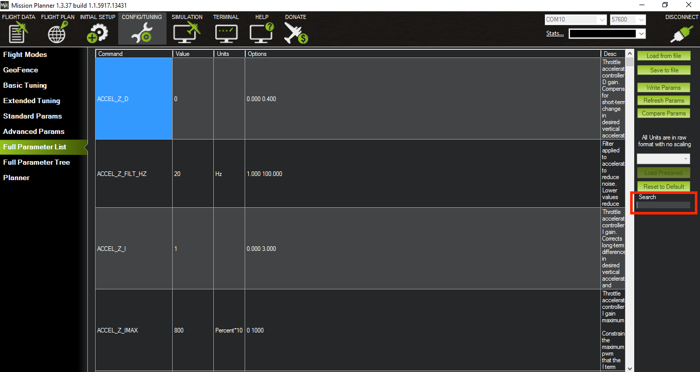
Go to the CONFIG menu.
-
Select Full Parameter List in the left side menu. To find the desired parameter quickly, use a search box on the right (highlighted in red).
cautionIf you are working with Pixhawk, reboot it each time you set a parameter for a change to take effect. Unplug it and plug in back to the USB port again.
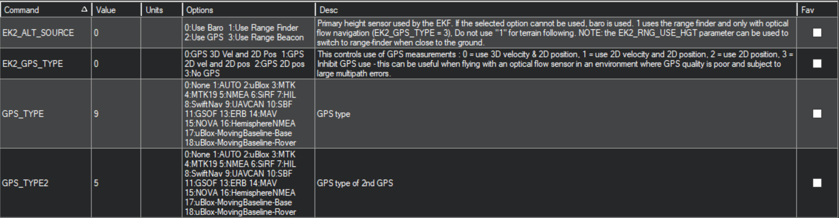
-
Set GPS_TYPE2 parameter to 5 - NMEA or 13 - ERB. This will enable the second GPS input.
noteMake sure to select the same parameter you set in Position streaming on your rover.
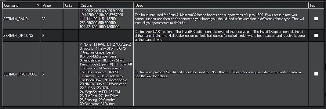
-
Set SERIAL4_BAUD parameter to the same baud rate as chosen in Emlid Flow Position streaming settings. Note the options corresponding to the different baud rates.
-
Set SERIAL4_PROTOCOL parameter to 5 - GPS.
-
Set GPS_AUTO_SWITCH to 1 - Enabled. Autopilot will automatically switch between the two GPS receivers picking the one with better solution.

-
Set GPS_INJECT_TO parameter to 1. Here, it stands for the second GPS input. If you configured Reach as the first input, set this parameter to 0.

If Mission Planner reports Bad GPS Signal Health error, make sure GNSS update rate on Reach is 5 Hz or higher.
Set Up Your Base
Now you need to configure your Reach base to send the corrections. Follow the steps below:
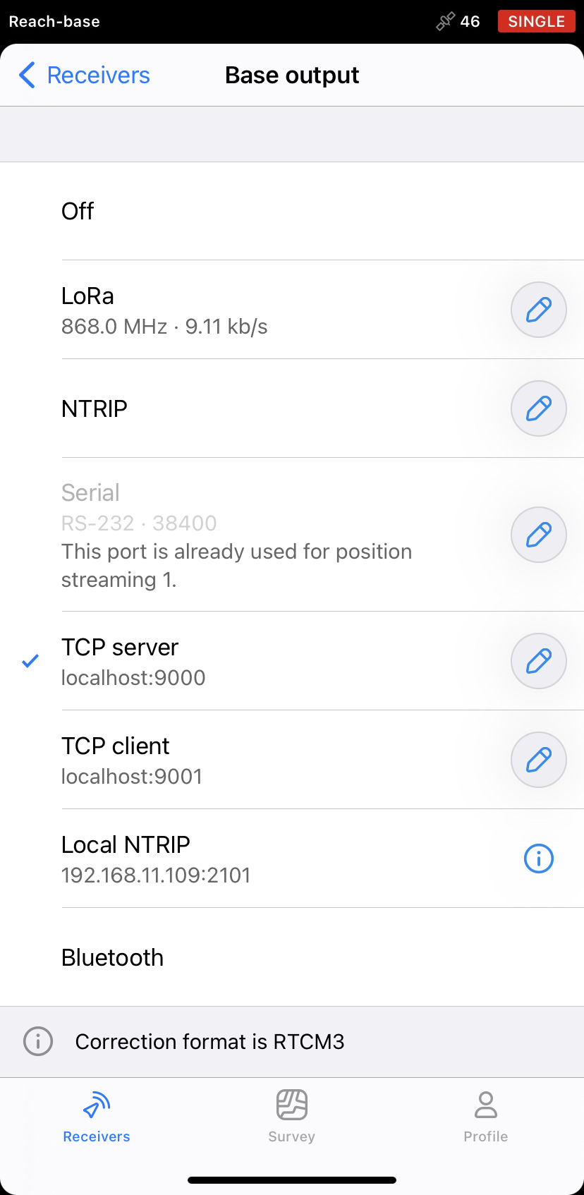
-
Open Emlid Flow and connect to your base.
-
Tap Base output.
-
Choose TCP server.
-
Set 9000 as a port.
-
Tap Save button to save settings.
Configure Mission Planner to Inject Corrections Into Telemetry
To enable and configure GPS inject options in Mission Planner, you need to open a window with advanced GCS settings. Do as follows:
-
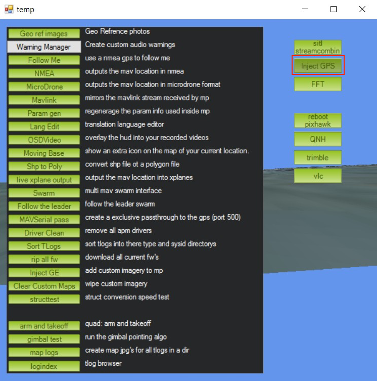
Press CTRL+F button combination. This will open a window with advanced GCS settings.
-
Click Inject GPS button on the right.
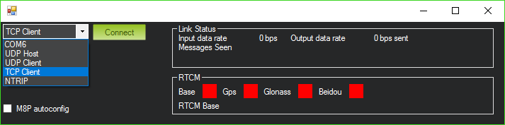
After that, in the new window, you need to choose parameters for base connection. Follow the steps below:
-
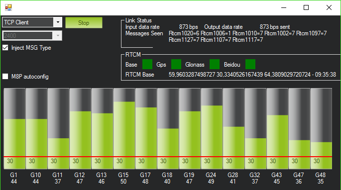
Choose TCP Client and press Connect.
-
Enter the base Reach's IP address and press OK.
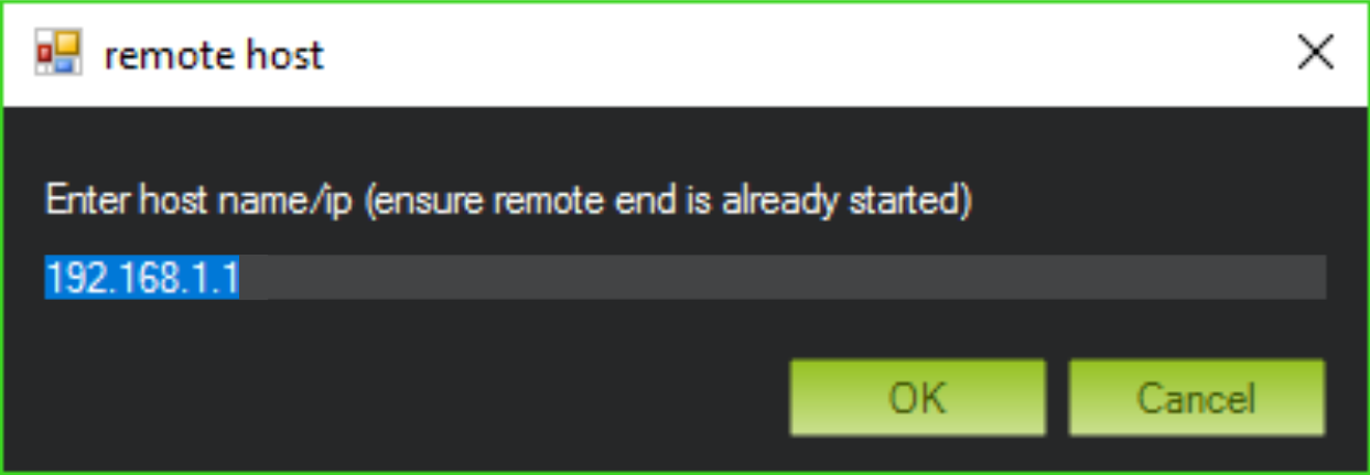
-
Enter the server port number and press OK.
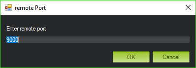
-
Finally, check the corrections are coming in.