Configuration
Auxiliary function switches
Auxiliary function switches on channels 5-8 are still not supported and could lead to erroneous PWM generation on motors' channels.
danger
Do not set auxiliary function switches to RC5..8!
Relay Switch
Relay is an digital output pin that can be switched between 0 volts and 3.3V. Similar to a servo it allows the flight controller to invoke some action from another device on the vehicle.
note
This feature is available on ArduCopter, ArduPlane, and ArduRover.
You need to specify RELAY_PIN parameter in Full Parameter List in Mission Planner or in Parameters in QGC. Use the following table for this:
| Name | Digital Pin number |
|---|---|
| PWM1 | 0 |
| PWM2 | 1 |
| PWM3 | 2 |
| PWM4 | 3 |
| PWM5 | 4 |
| PWM6 | 5 |
| PWM7 | 6 |
| PWM8 | 7 |
| PWM9 | 8 |
| PWM10 | 9 |
| PWM11 | 10 |
| PWM12 | 11 |
| PWM13 | 12 |
| PWM14 | 13 |
| IO17 | 14 |
| IO18 | 15 |
| LED RED | 16 |
| LED GREEN | 17 |
| LED BLUE | 18 |
danger
Don't set digital pin to PWM channel used for control servos!
Second compass configuration
Navio2 contains two compasses: AK8963 and LSM9DS1. The latter has lower offsets and set as primary. AK8963 is disabled by default.
We will walk you through the steps required to perform the onboard compass calibration.
Onboard calibraton
Navigate to Initial Setup - Mandatory Hardwawre - Compass
- If you use two compasses tick Use this compass in Compass #2 tab.
- Click on Start button in Onboard Mag Calibration tab.
- Rotate your drone around all axis.
- Wait for calibration to complete (the process ends with a message similar to one on the picture attached below).
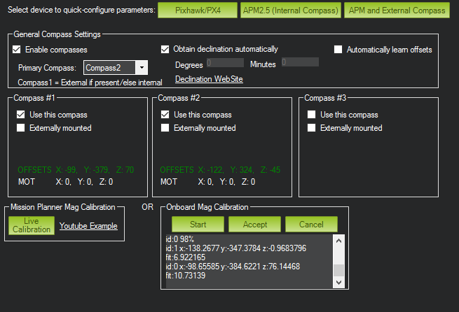
- Click Accept button (there is a change nothing is going to happen in responce).
- Swith to another view and get back to Compass Calibration.
- Verify that offsets that have been calculated in the previous steps have been saved.
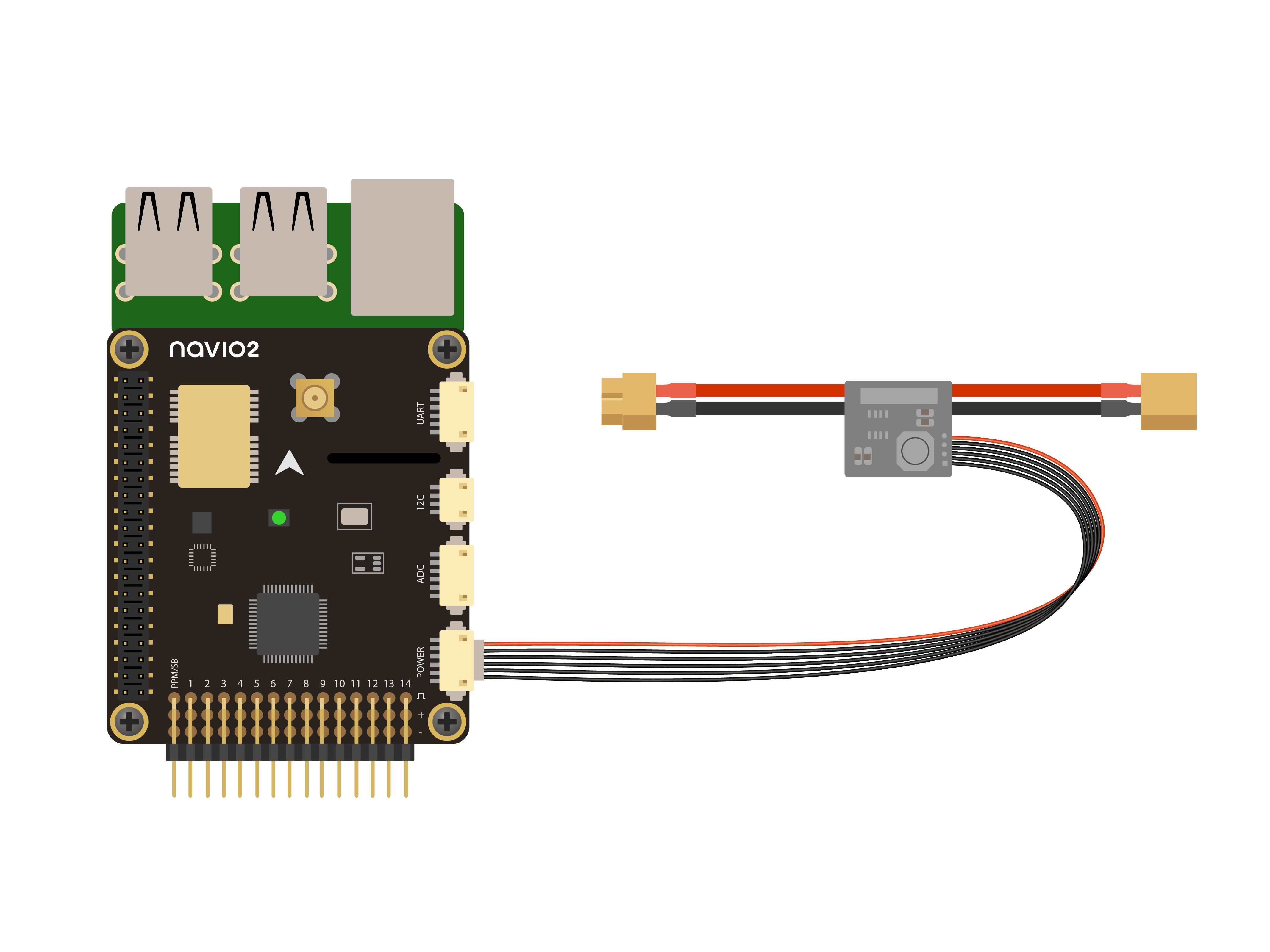
Voltage and current sensing
If you have original power module connected to Navio2, you can get battery voltage and curent readings from it.
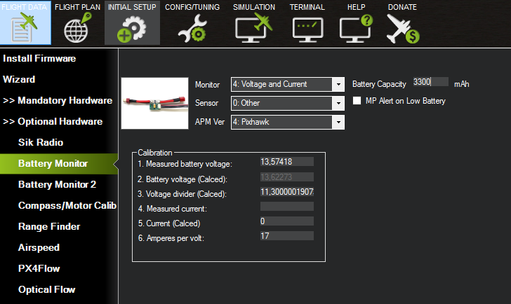
To setup voltage and current measurement for ArduPilot, do this:
- Switch to Initial Setup tab in Mission Planner.
- Navigate to Optional Hardware - Battery Monitor section.
- Set Monitor, Sensor and ArduPilot Ver options as shown below.
Now you need restart both ArduPilot and connection between Mission Planner and ArduPilot:
- Use Ctrl-F shortcut to open Temp Screen.
- Press reboot pixhawk button.
- On the main menu bar press DISCONNECT and then CONNECT.
When everything is done, you should see voltage and current values on Flight Data screen.
Also you can check in full parameter list that:
BATT_CURR_PIN 3
BATT_VOLT_PIN 2
Further configuration
As other ArduPilot configuration procedures are very similar for most ArduPilot-running autopilot hardware, please use the ArduPilot documentation: