Collect lines
Upgrade your surveying experience with coding, linework, background maps, and localization
This guide shows how to collect points to store their positions in a project using Emlid Flow.
Overview
Collector in Emlid Flow allows creating linework with as many points as you want. With linework, you can measure linear objects like fences, roads, and pavements, and store their positions in a project for further in GIS software.
Workflow
Collecting lines
- Emlid Flow
To collect lines using Emlid Flow, follow the steps below:
-
Open Emlid Flow and connect to your Reach.
-
Go to the Survey tab and open or create a project.
tipTo learn how to create a project, check the Create or import project guide.
-
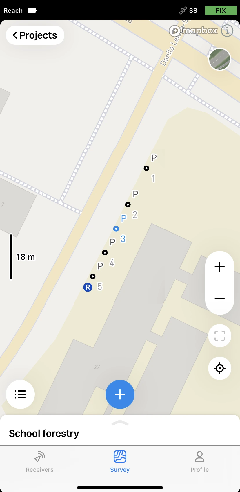
Tap the Plus button to open the Collector menu.

-
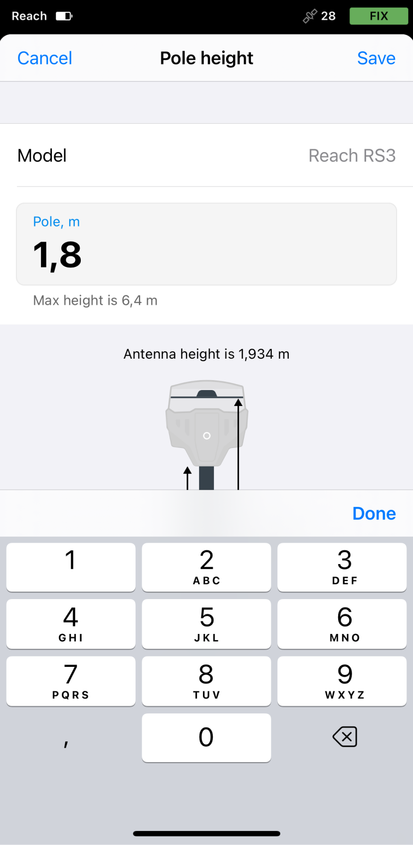
Set the
pole height. By default, this parameter is set to 1.8 m.When preparing for point collection, configure the height of your survey pole in Emlid Flow. It will help the app to automatically calculate the antenna height.
-
note
This step is optional.
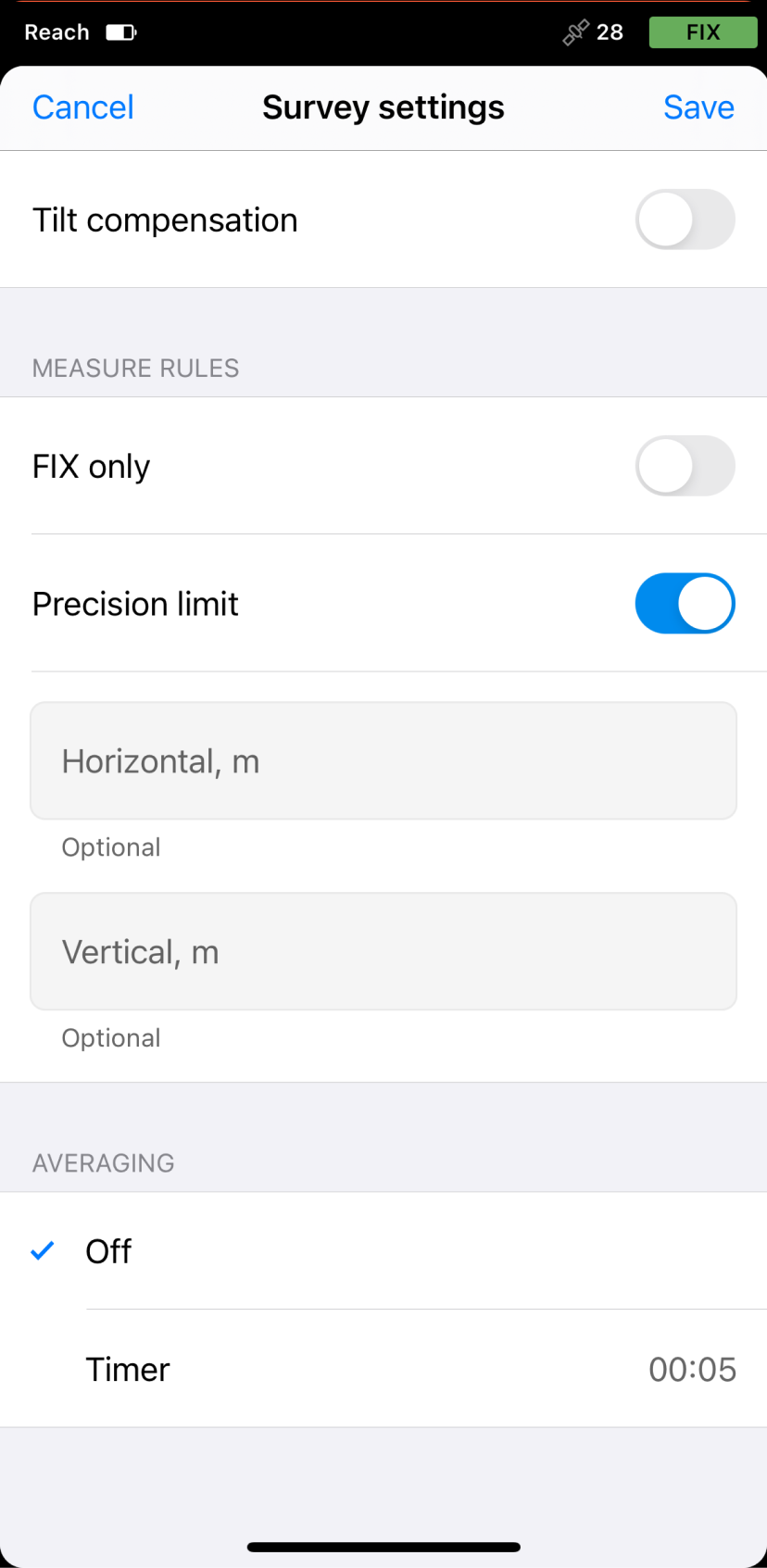
To configure survey settings, tap the gear icon and enable or configure the following options:
- Only for Reach RS3: Tilt compensation. You can turn on and off tilt compensation.
- Precision control. You can set your receiver to collect data only when your Reach has the FIX solution status.
Solution status defines the precision that can be achieved at the moment. There are three solution statuses you can see when working with Reach devices.
SINGLE means that the rover has found a solution relying on its own receiver and base corrections are not applied. Precision in standalone mode is usually at the several-meter level.
FLOAT means that the rover receives corrections from the base but cannot resolve all ambiguities, and in this case, the precision is usually at the submeter-level.
FIX means that the rover using corrections from the base resolved the ambiguities in its positional calculation and achieved the solution with the centimeter-level precision.
- Precision limit. You can set horizontal and vertical precision tolerance values. The units for these values are the same as those set for your project.
- Timer. You can specify the time interval of data collection.
-
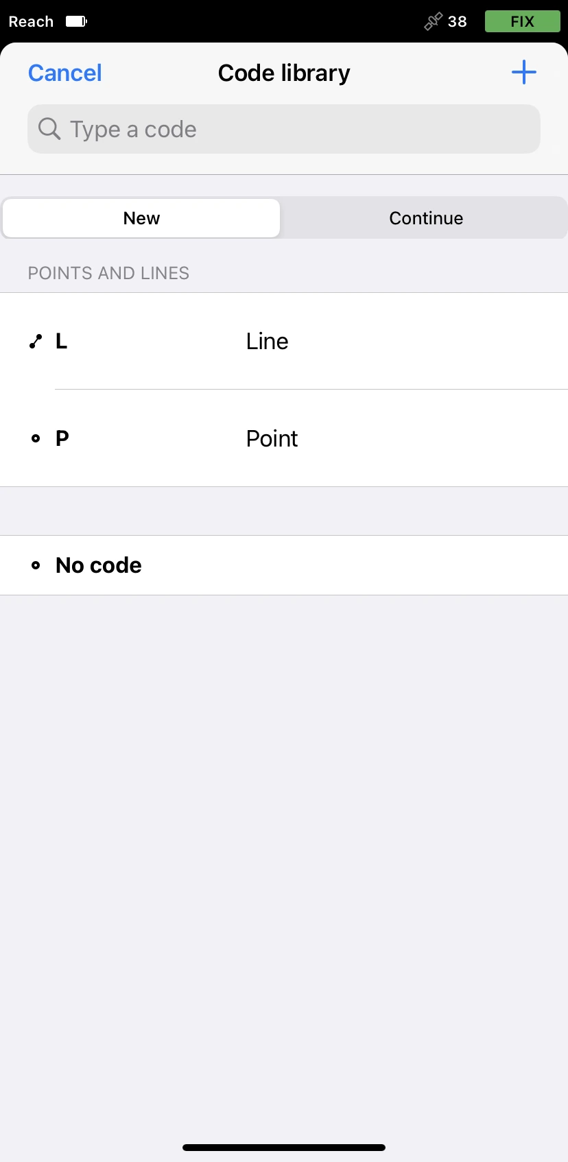
Tap the Code selector button and select the Line survey code.
-
Collect the first point of a line.
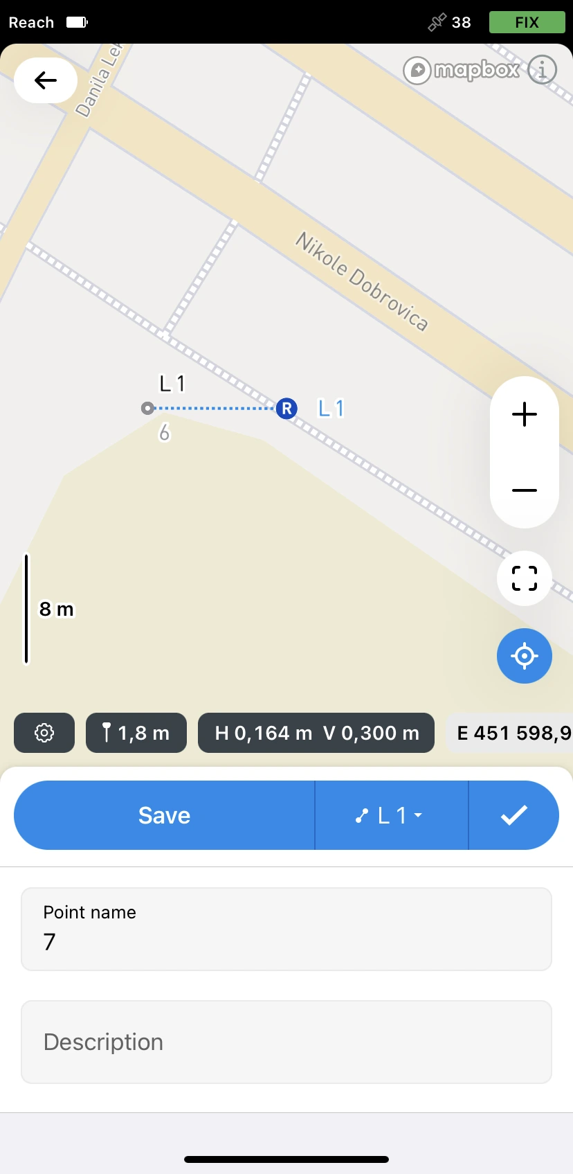
-
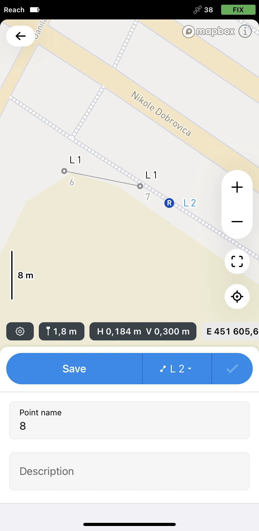
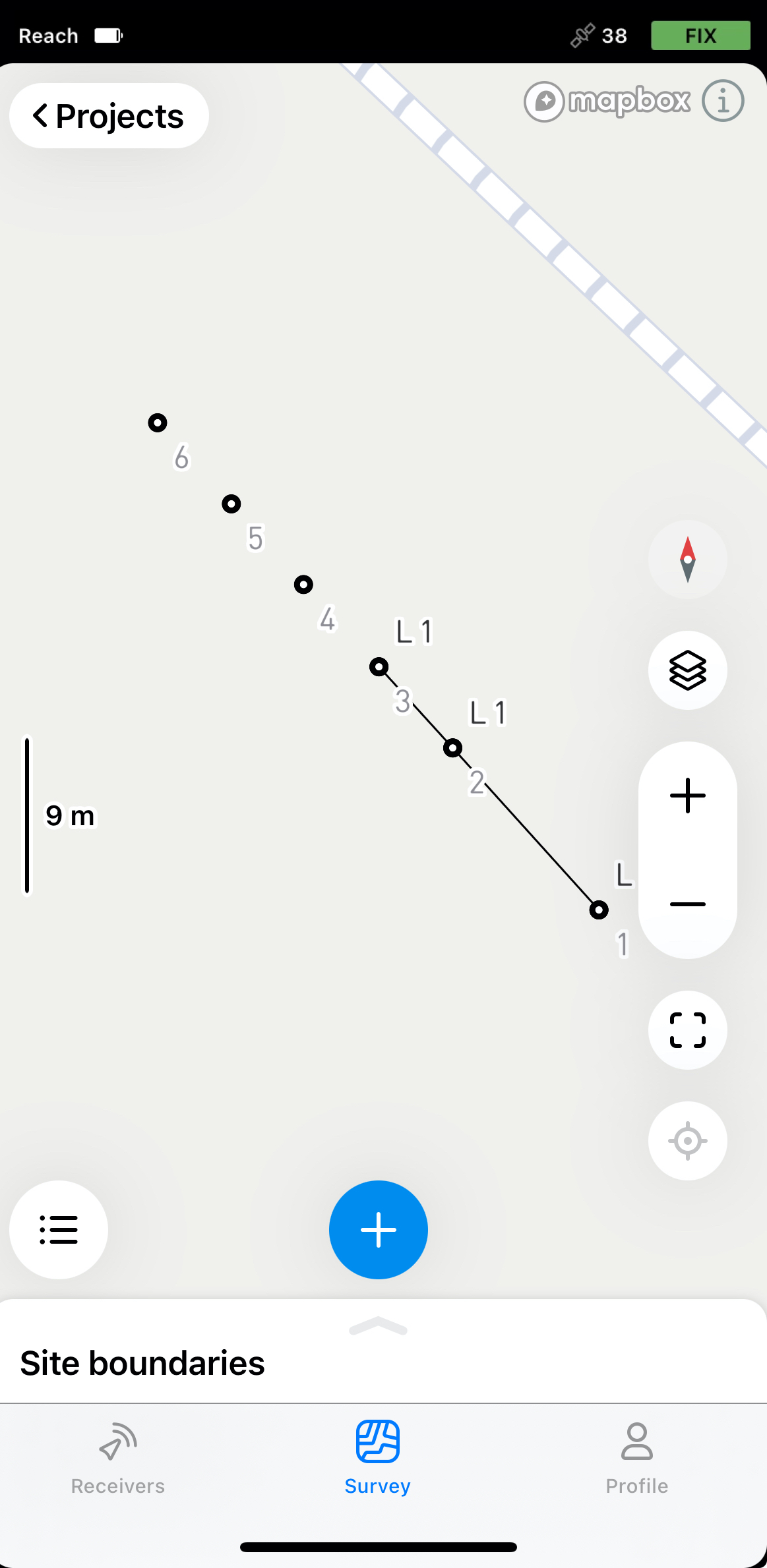
Go to the second point of the line and collect it. Once there are at least 2 points, the app will connect them with a line.
tipYou can collect as many points as you want in a single line.

-
Tap the Check button to finish collecting the line.

You can continue collecting lines to store their positions in the project.
Continuing existing lines
Every line in your project can be continued after it was collected in the following way:
-
On the Project view screen, tap the Plus button to open the Collector menu.
-
Tap the Code selector button and switch to the Continue tab.
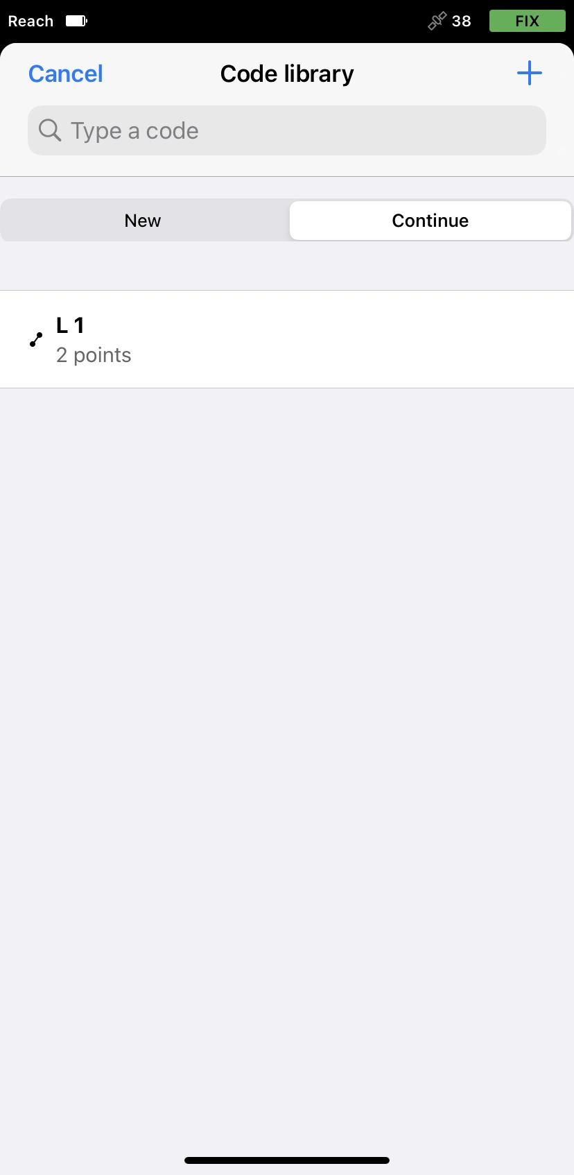
-
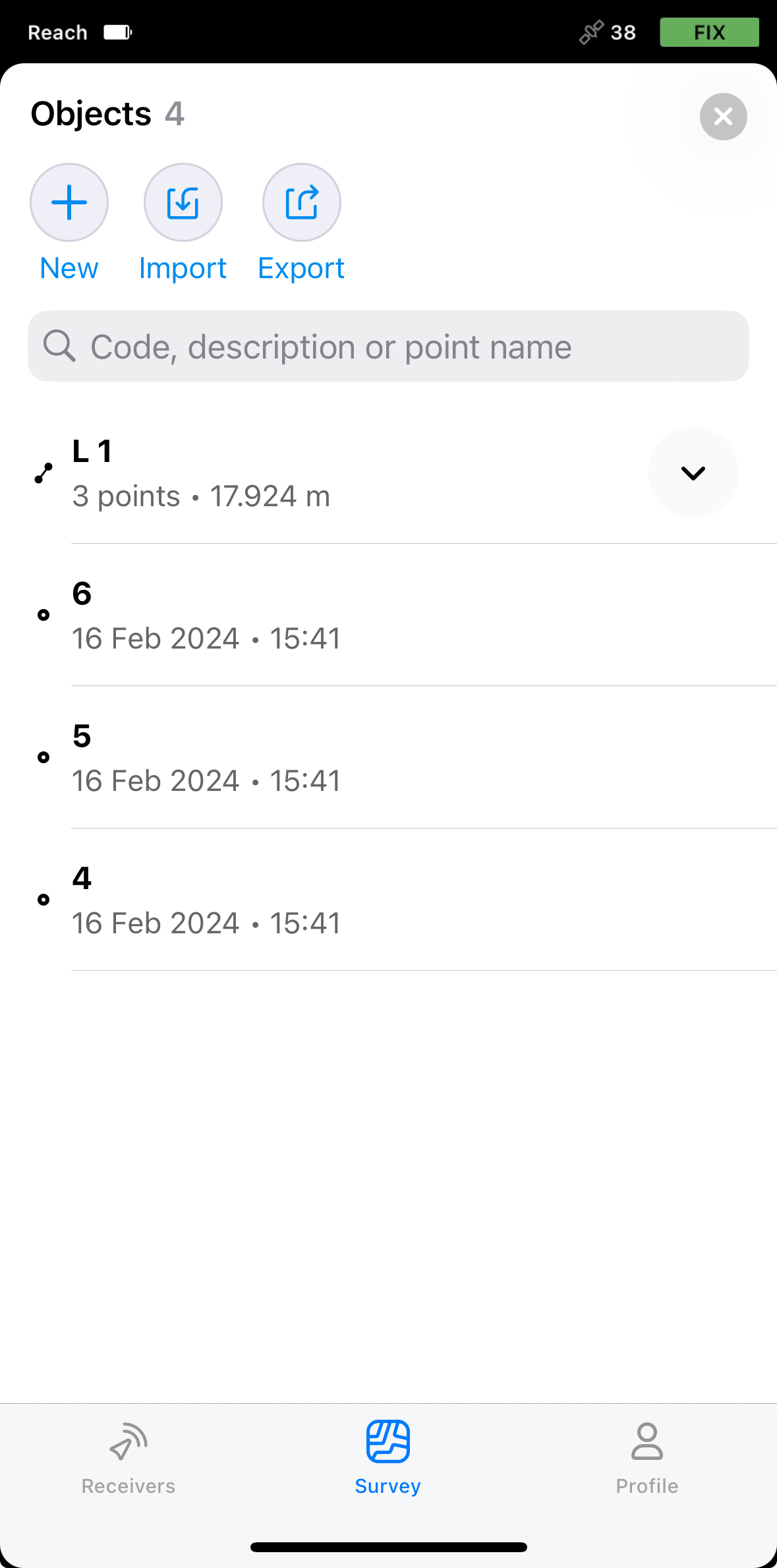
Select the line you want to continue. The app will bring you back to the Collector menu with the line’s code selected.

-
Collect additional points of the line. To finish collecting the line, tap the Check button.
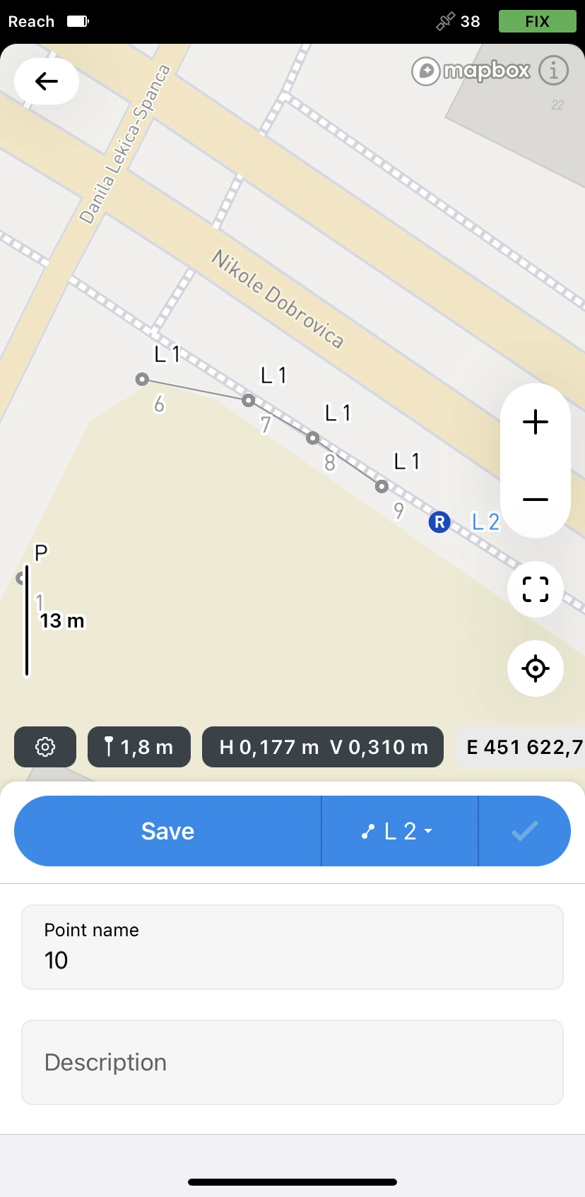
You can now move to the next line you want to continue or proceed to collect new lines to store their positions in the project.
Checking information about lines
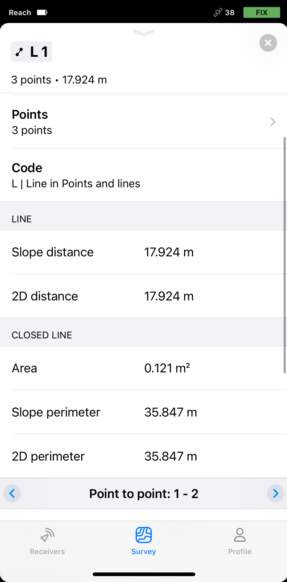
In Emlid Flow, you can check the detailed information about the collected lines. The information provided depends on the number of points in the collected line—if your line consists of 3 or more points, you can also check information about its segments and a possible closed line.
Currently, closed lines are only used for calculations and are not available as an object and cannot be imported.
To learn more about collected lines, do as follows:
If one or more of the line points are missing global or local coordinates, the information won’t be displayed.
-
Open your project in Emlid Flow.
-
Choose the required line from the list of objects or tap it on the map.
-
Swipe the drawer up to see the information about the chosen line.
- If your line consists of two points, you'll see the following information:
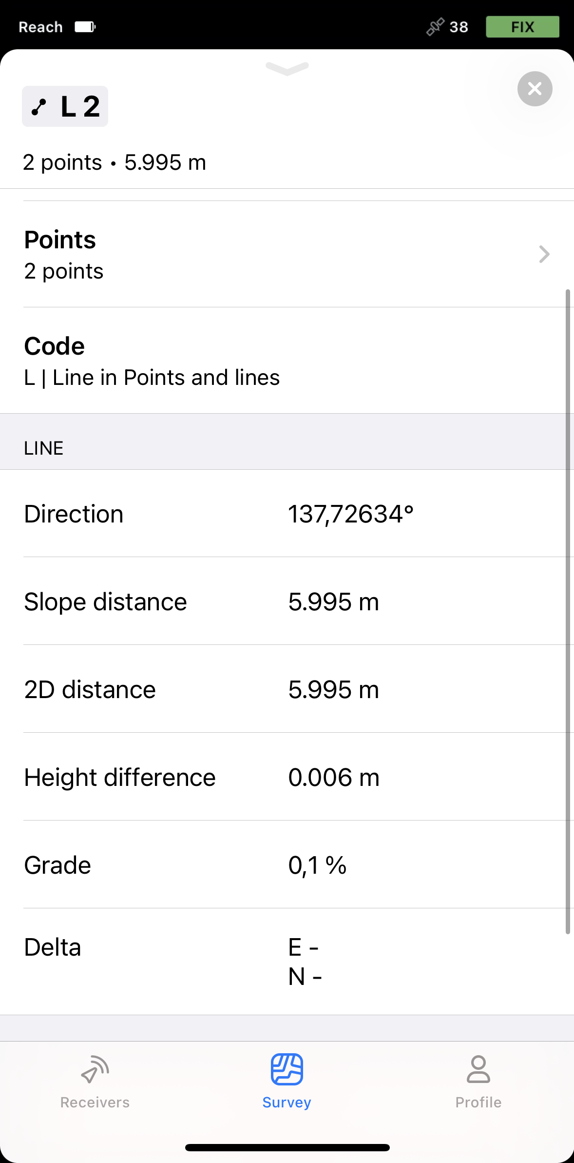 noteDelta E/Nis available only for lines in local coordinates.
Delta E/N between points A and B is the difference in their coordinates along the corresponding Easting and Northing axes.
- If your line consists of more than 2 points, you'll see the following information:
 note
noteMake sure to check if the closed line doesn’t form self-intersecting polygons. In this case, the closed line information may be inaccurate.
Depending on the
Coordinate system is a coordinate-based local, regional or global system used to locate geographical entities. A spatial reference system defines a specific map projection, as well as transformations between different spatial reference systems.
Ground distance is the distance measured on the actual surface of the Earth, taking the mean elevation of the measured points into account.
True North azimuth is the angle ranging from 0 to 360 degrees measured clockwise between True North and the direction to a point of interest.
Grid distance is the distance measured on the projection flat plane.
Grid North azimuth is the angle measured clockwise between a line parallel to the central meridian, and the direction to a point of interest (a straight line between two points on the projection flat plane).